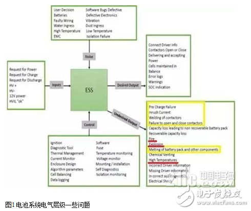
Electric vehicles (EVs) often face battery short-circuit issues after prolonged use, and these problems can be quite serious. How can we prevent or even eliminate this issue? Today, we'll explore how to overcome battery short-circuit challenges and discuss effective protection design strategies.
**Single Cell Test:**
According to the GBT31485 standard, a short-circuit resistance of 5 milliohms is required for 10 minutes. In practice, the test should be based on the minimum cell connection to simulate real-world conditions accurately.
As shown in the table above, short-circuit or overcurrent situations occur when any level—single cell, module, half-pack, or full battery pack—exceeds its rated discharge capacity.
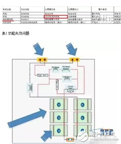
**Figure 2: Short-Circuit Requirements for Each Level**
**Battery System Short-Circuit Test:**
Following GBT31476.3, the short-circuit resistance should be 20 milliohms for 10 minutes.
**MSD Breaking Half-Pack Test:**
This test focuses on extreme scenarios where the system fuse fails to activate in the MSD (Main Switch Disconnect), testing the overall system design under such conditions.
**Module-Level Short-Circuit Test:**
Again, following GBT31485, the short-circuit resistance is set at 5 milliohms for 10 minutes. The simulation should be adjusted based on the actual minimum cell configuration.
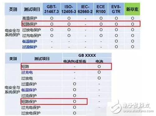
**Table 2: Existing Domestic and International Standards and Future GB**
Different levels require different approaches:
1. **BMS (Battery Management System):** It cuts off the contactor based on current detection. During a short-circuit, the contactor must disconnect at least once.
2. **Internal Fuse in MSD:** Careful consideration must be given to the fuse selection within the MSD to ensure it functions correctly during a fault.
These measures are typically implemented at the Pack level. At the Module level, designs like J-bar punching or other structural solutions are used to manage short-circuit risks effectively.
The actual effect of a half-pack short-circuit is very clear and visible.
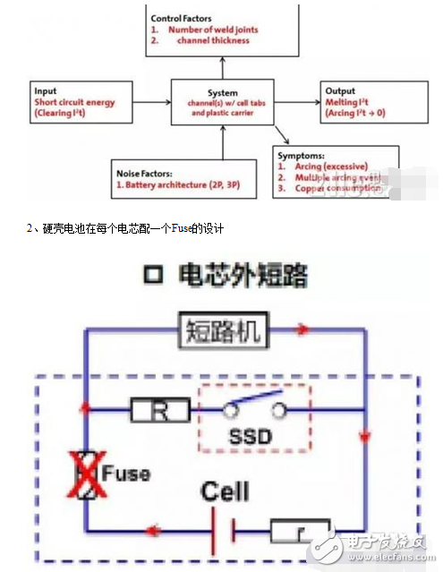
**Cell-Level Fuse Design:**
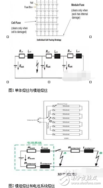
Each cell can have an internal fuse. When a short circuit occurs, the fuse breaks the current loop, providing localized protection.
Soft-pack batteries often use individual fuses per cell, or consider the Tab's state under fault conditions. This design is both practical and innovative, addressing both normal and overcurrent scenarios.
After understanding the regulations, experimental requirements, and design concepts related to short-circuit protection, it’s essential to validate the design through testing.
**1. Layered Fuse Refinement:**
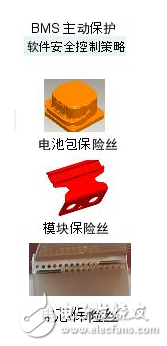
Graded fuse protection divides the entire battery pack into four layers for better control:
- **Cell Fuse:** Protects against internal short circuits, placed on the cell tab or busbar.
- **Module Fuse:** Prevents module-level faults, often overlooked by some manufacturers.
- **System Fuse (Half-Pack):** Prevents external short circuits at the system level.
- **Vehicle-Level Fuse:** Located near the power distribution unit to protect the entire vehicle from large currents.
**2. Fuse Design Considerations:**
The time-current curve of the fuse must be analyzed carefully. The normal operating range (green area) allows safe current flow, while the abnormal range (red area) triggers the fuse to disconnect the battery from the system.
Short-circuit durations should be in the tens of milliseconds to isolate the fault quickly. Prolonged short circuits can lead to overheating and damage.
The short-circuit current varies depending on the battery's state of charge (SOC) and end-of-life (EOL) status, so these factors must be considered in the design.
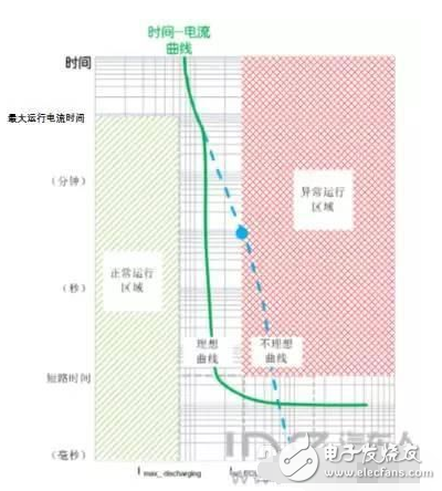
**Figure 3: Short-Circuit Design Considerations**
In practical applications, parameters need to be converted and matched with the fuse’s time-current characteristics. Different fuses have different performance curves, and their behavior must be tested and optimized.
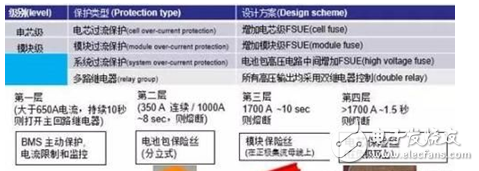
**Figure 4: Multi-Level Protection Description**
By analyzing various fuse curves, engineers can optimize the protection strategy for each level of the battery system.
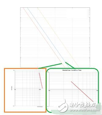
**Figure 5: Multi-Level Time-Fracture Decomposition**
Two main methods are used: selecting appropriate fuses and designing them based on specific requirements, as well as integrating overcurrent detection and short-circuit protection strategies within the BMS.
It’s important to understand the grading strategy of fuses, their mechanism, and durability. These aspects will be discussed in detail later.
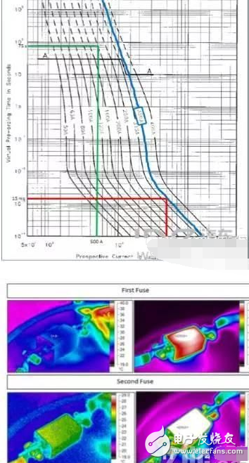
**Figure 6: Fuse Blown in Main Fuse**
When designing your own system, multiple factors must be taken into account. This topic will be expanded further in future discussions.
**3. Utilization Considerations:**
Battery systems must also consider layout and fuse placement. Parallel connections are still a key factor in energy storage systems, making internal design critical.
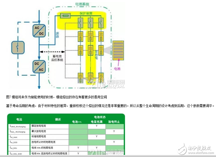
**Table 1: Current Different State Decomposition Table**
**Summary:**
Fuse design requires extensive testing and must align with the actual working conditions of the vehicle. Poorly designed fuses may fail to provide protection or blow frequently, leading to system instability. A well-planned and tested approach ensures both safety and reliability.
Industrial PC
Industrial PC, a Fan-less cooling and smallest case allows for space-saving design, so it can be placed horizontally or vertically to offer you best placement options, and you`ll set it on a desk and forget its even there.
An industrial PC (IPC) is a specialized computer designed to withstand the harsh environments and demanding requirements of industrial settings. Unlike consumer-grade PCs, industrial PCs are built to provide reliable and long-lasting performance in challenging conditions.
Performance and Features
Industrial PCs are available in a wide range of configurations to meet the diverse needs of industrial applications. They can be equipped with powerful processors, large amounts of memory, and high-capacity storage to handle demanding tasks such as data acquisition, process control, and machine vision.
Many industrial PCs also feature multiple expansion slots and I/O ports, allowing for easy integration with a variety of industrial devices and sensors. These ports may include serial ports, USB ports, Ethernet ports, and digital I/O ports.
Some industrial PCs also offer advanced features such as touchscreens, wireless connectivity, and remote management capabilities. These features can enhance usability and convenience in industrial settings, allowing for easy access to data and control of industrial processes.
Low cost mini pc, Personal computer,Industrial PC,Mini pc windows,Fanless Industrial PC
Shenzhen Innovative Cloud Computer Co., Ltd. , https://www.xcypc.com