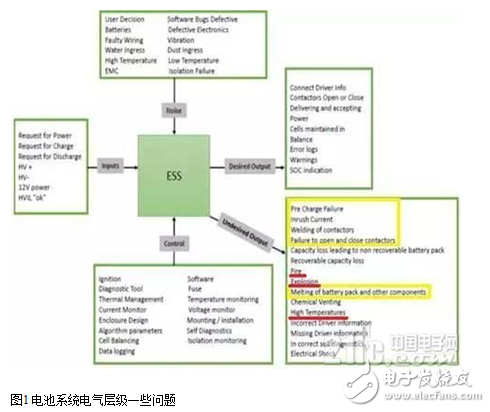
Electric vehicles (EVs) often face battery short-circuit issues after prolonged use, and the consequences of such failures can be quite severe. To address this challenge, it's essential to understand how to prevent or eliminate these occurrences effectively. In this article, we will explore advanced methods for overcoming short circuits in pure electric batteries and discuss key design solutions for protection.
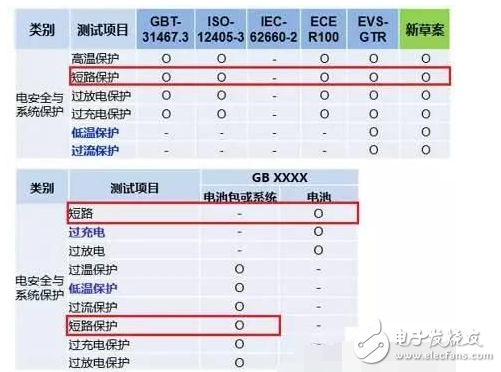
One of the first steps in evaluating short-circuit resistance is conducting single-cell tests according to the GBT31485 standard. The test requires a short-circuit resistance of 5 milliohms for a duration of 10 minutes. However, the actual unit must be tested based on the minimum cell connection to ensure accurate simulation of real-world conditions.
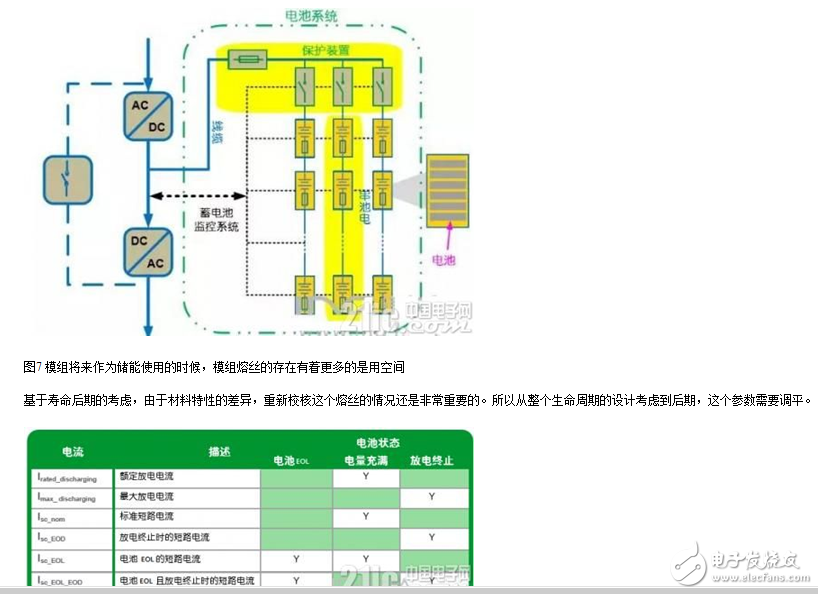
As shown in the table below, short-circuit and overcurrent events are defined by each level—single cell, module, half-pack, and full battery pack—exceeding their rated discharge capacity.
In addition to individual tests, battery system short-circuit testing follows GBT31476.3, which specifies a short-circuit resistance of 20 milliohms for 10 minutes. This ensures that the entire system can withstand extreme conditions.
Another critical test involves the MSD (Main Switch Device) breaking half-pack scenario. This test simulates a worst-case situation where the system fuse fails, allowing engineers to evaluate the robustness of the overall design.
Module-level short-circuit tests also follow GBT31485 guidelines, with a 5 milliohm resistance and 10-minute duration. These tests are crucial for ensuring that each component within the battery system can handle potential faults without causing larger system failures.
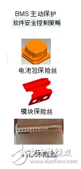
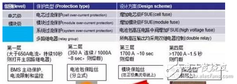
Different levels require different protection strategies:
1. **BMS-based contactor cutoff**: The Battery Management System (BMS) must detect current anomalies and cut off the contactor promptly.
2. **Internal fuse design in MSD**: Fuses inside the MSD need careful selection to ensure they activate under fault conditions.
3. **Module-level protection**: At the module level, designs such as J-bar punch-throughs help isolate faults before they escalate.
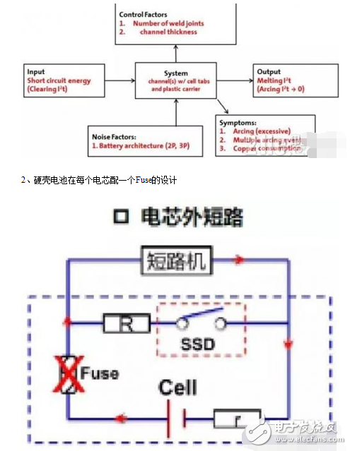
4. **Cell-level fuses**: Each cell should have an internal fuse to disconnect the circuit during a short-circuit event.
Soft-pack batteries, for example, may use individual cell fuses or consider the condition of the tabs under high-current scenarios. This design approach helps manage both normal and overcurrent situations effectively.
After establishing protection regulations and experimental requirements, it’s important to confirm the design values through testing. One key strategy is **graded fuse protection**, which divides the battery pack into four layers for comprehensive fault isolation.
- **Cell-level fuse**: Prevents damage from parallel cell shorts.
- **Module-level fuse**: Often overlooked but critical for isolating module-specific faults.
- **System-level fuse (half-pack)**: Protects against external short circuits.
- **Vehicle-level fuse**: Ensures power distribution safety.
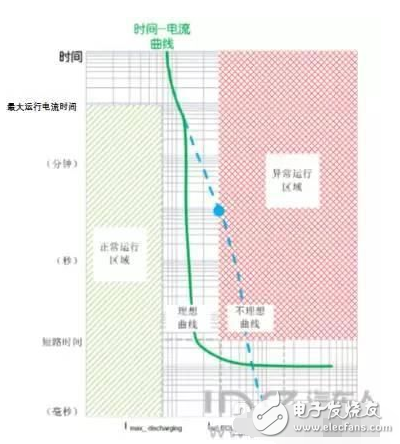
The time-current curve of a fuse is another critical factor. The fuse should allow normal current flow (green area) while quickly cutting off when an anomaly occurs (red area). Short-circuit durations should be limited to tens of milliseconds to minimize energy release and potential damage.
Designers must also consider the state of charge (SOC) and end-of-life (EOL) conditions, as these affect short-circuit current behavior. Additionally, factors like ambient temperature and pulse currents influence fuse performance.
When designing a multi-level protection system, two main approaches are typically used: selecting appropriate fuses and integrating overcurrent detection and short-circuit strategies into the BMS. Testing and analyzing different fuse specifications is essential to ensure compatibility with the vehicle’s operational conditions.

Finally, the location and placement of fuses within the system play a vital role. For instance, in energy storage systems with parallel connections, proper fuse positioning is crucial to maintain stability and safety.
**Summary:**
Fuse design requires extensive testing and must align with the actual working conditions of the vehicle. A poorly designed system may fail to protect the battery or cause frequent fuse blowouts. Therefore, careful planning, simulation, and validation are essential to ensure reliable short-circuit protection in EV battery systems.
A capacitive panel PC is a computing device that features a touch-sensitive screen using capacitive touch technology. Unlike resistive touch screens, capacitive screens respond to the electrical conductivity of the human body, allowing for more accurate and responsive touch interactions.
Capacitive panel PCs are a revolutionary technology that combines the functionality of a traditional computer with the intuitive touch capabilities of a tablet. These devices offer a seamless user experience, making them ideal for a wide range of applications in various industries.
The smooth and responsive touch interface of capacitive panel PCs provides a more intuitive and natural user experience. Users can easily navigate through applications, scroll, zoom, and perform gestures with ease.
Capacitive touch screens are also more durable than resistive touch screens, as they do not rely on pressure to register touches. This makes them less prone to damage and wear over time.
Capacitive touch technology is known for its fast response times and high accuracy. This results in a more seamless and efficient computing experience, especially when running resource-intensive applications or multitasking.
Capacitive panel PCs can be used in a variety of settings, including industrial, commercial, educational, and healthcare environments. They are suitable for applications such as point-of-sale systems, digital signage, kiosks, and medical devices.
Capacitive Panel PC,Capacitive Screen Panel PC,Capacitive Touch PC
Shenzhen Innovative Cloud Computer Co., Ltd. , https://www.xcypc.com