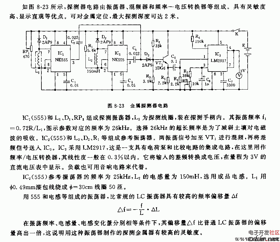
Explore the detailed 555 metal detector circuit diagram. This schematic provides a clear overview of how a basic metal detection system works using the popular 555 timer IC. The design is simple yet effective, making it a great project for electronics enthusiasts and beginners alike.
The 555 timer is used in this circuit to generate oscillations that are sensitive to changes in the magnetic field caused by nearby metal objects. When a metal object enters the detection zone, it disturbs the electromagnetic field, triggering a response from the circuit. This can be used to activate an alarm or a visual indicator, depending on the setup.
This type of circuit is commonly used in DIY metal detectors, security systems, and even in educational projects to demonstrate the principles of analog electronics. Whether you're looking to build your own metal detector or simply want to understand how these circuits work, this diagram is a valuable resource.
If you're interested in building your own version, make sure to gather all the necessary components, such as resistors, capacitors, transistors, and a coil. Follow the wiring carefully and test the circuit step by step to ensure everything functions as expected. With some patience and attention to detail, you'll have a working metal detector in no time!
DongGuan BoFan Technology Co.,Ltd. , https://www.ufriendcc.com