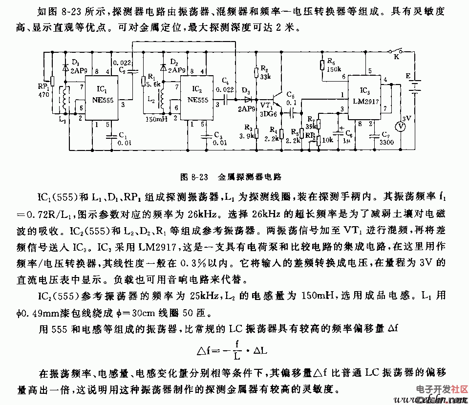
The 555 metal detector circuit diagram is a classic example of using the NE555 timer IC to create a simple yet effective metal detection system. This type of circuit is widely used in educational projects and DIY electronics due to its simplicity and low cost. The basic principle involves generating an oscillating signal that interacts with a coil. When a metal object comes near the coil, it disrupts the magnetic field, causing a change in the oscillation frequency. This change is then detected by the circuit, triggering an alarm or a visual indicator.
In this design, the 555 IC is configured as an oscillator, typically in an astable mode, which means it continuously switches between high and low states without any external trigger. The coil acts as an inductor, and when a metal object approaches, it alters the inductance, thus affecting the frequency of the oscillator. A comparator or a transistor can be used to detect this change and activate a buzzer or LED.
This circuit is not only a great learning tool for understanding how electronic components work together but also a practical project for those interested in building their own metal detectors. It's often used in schools and hobbyist communities to teach fundamental concepts of electronics and signal processing.
DongGuan BoFan Technology Co.,Ltd. , https://www.ufriendcc.com