Below is the circuit diagram of a Fire Alarm System, specifically featuring three different schematic views for better understanding.
The fire alarm circuit diagram is an essential part of any safety system, designed to detect smoke or heat and trigger an alarm. This schematic includes key components such as sensors, control units, and output devices like sirens or lights.

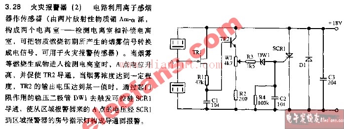
This image shows the main layout of the fire alarm system, including wiring connections and component placements.
This second schematic provides a more detailed view of one of the three sections, focusing on the sensor and signal processing unit.

The final diagram highlights the control panel and output stage, showing how the system communicates with external alarms and indicators.
If you're working on a similar project or looking to understand how these systems function, studying these diagrams can be very helpful. They provide a clear visual representation of how each component interacts within the overall system.
Black safety cone road cone,Black Omnidirectional Antenna,Black Transmitting Antenna
Mianyang Ouxun Information Industry Co., Ltd , https://www.ouxunantenna.com