Abstract : The pet intelligent feeding system is an efficient remote feeding system that can remotely control the pet's scientific feeding and feeding through WEB and mobile terminals (tablet, mobile phone). The S3C6 410 is the core processor, the infrared CCD camera is the video acquisition module and the TVP5150 is the video decoder. The highly integrated embedded real-time video acquisition platform is built. On this basis, the pet intelligent feeding system is designed. The design has the characteristics of small size, low cost, low power consumption, high stability, good safety and convenient operation, which satisfies the needs of intelligent science feeding pets. In this paper, a video capture driver design scheme suitable for the feeding system is proposed. Under the kernel of Linux 3.0.1, the driver is written based on the latest standard of V4L2 for processing video devices under Linux. The experiment proves that the scheme can successfully realize the collection of video data.
This article refers to the address: http://
With the rapid development of China's social economy, the process of urbanization is accelerating. China's national living standards have been continuously improved, and China's pet industry has also experienced rapid development. Problems such as the closure, personalization and aging of urban life have become increasingly prominent. The way of leisure, consumption and emotional sustenance in people's lives is also diversified. The breeding of family pets has become a new way of life for urban residents.
Pet feeding and care are often the most concerned issues for pet owners. At present, pets mainly rely on manual feeding. The pet care system also stays in the mode of special care and pet store hosting. The existing pet care device only solves the simple aspect of not letting the pet go hungry, but does not solve the interaction requirement between the pet and the owner when the owner is not at home. The problems that the owner cares about, such as what the pet is doing now, whether there is eating, how the health of the pet is, etc., the satisfaction of these psychological demands is a problem to be solved by a pet care system. Today's equipment is not enough to meet this demand.
At present, there are only a few family pet care systems. The products of the nursing system are single-function. They simply measure the pet environment and feeding. They can not meet the needs of users who can feed pets remotely and watch pets eating and activities online. In recent years, with the rapid development of embedded technology, embedded systems have matured and been widely used. Combining embedded systems with Web technologies, introducing Web technologies into measurement and control systems, and implementing remote measurement and control systems based on embedded Web servers. Have a good application prospects. The remote measurement and control system using Boa as a Web server under the embedded Linux platform can achieve the above requirements. The pet intelligent feeding system equipped with a highly integrated embedded real-time video acquisition platform can well meet the different needs of customers. Through the infrared CCD camera on the embedded real-time video capture platform, pet owners can use the smart phone, tablet computer, PC computer, etc. to control the pet's eating and activities while watching the pets during the day or night.
In this system, the driver is used to complete the interaction between the user and the hardware. It is a prerequisite for the normal operation of the hardware device and plays an indispensable role. This paper proposes a video capture system driver design scheme based on S3C64 10's Linux 3.0.1 kernel version, and has been successfully used in the pet intelligent feeding system, and received good results.
1 hardware system architecture
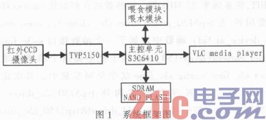
The pet intelligent feeding system is mainly composed of an image acquisition module, a video decoding module, a S3C6410, a feeding module, a water feeding module and a display module. The infrared CCD camera is used to collect the image of the pet's feeding and activity in the working state of the intelligent feeding system. Since the S3C6410 cannot recognize the collected PAL standard signal, it needs to do video decoding processing. Here, the Tvp5150 decoder introduced by TI is used. Convert the acquired PAL system signal into YCrCb format. S3C6410 is the core part of the whole system. The converted digital signal data enters the encoding and scaling device of the Camera unit through the encoded DMA channel. After being encoded by H264 with high encoding quality and compression ratio, it is saved to the buffer area opened by the user program, and then transmitted to the buffer area. In the live555 streaming server receiving program, live555 implements streaming and related processing of the encoded video stream, and finally displays it in real time through the streaming media player VLC media player embedded in the webpage. The feeding module in the system can realize the quantitative feeding of the food required by the pet, and the feeding module can realize the functions of automatic feeding and remote feeding. In addition, in order to facilitate the related processing of images, NAND FLASH is required for storing captured images. At the same time, common peripheral interfaces such as SDRAM, JTAG and power supply parts are indispensable parts in the development process. The highly integrated real-time video capture system thus built has a significant miniaturization effect. The overall framework of the system is shown in Figure 1.
1.1 S3C6410 Development Platform
The S3C6410 is a low-cost, low-power, high-performance microprocessor based on the 16/32-bit RISC ARM1176JZF-S core. It has a clock speed of up to 533 MHz, 4 G ROM and 512 M RAM, and is powerful and comparable to today's mainstream. smart phone. The S3C6410 integrates many powerful hardware accelerators such as video processing, moving image processing, display control and image scaling. It integrates Camera interface unit, system manager, LCD controller, timer, general purpose I/O port, I2C. Hardware peripherals such as bus interface, advanced OTG interface and mainstream NAND FLASH that can support SLC/MLC. The Camera interface unit directly related to the system consists of 7 modules: graphics multiplexer, capture unit, preview scaler, code scaler, preview DMA channel, coded DMA channel and SFR (special function register). The two DMA channels in the system are: preview DMA channel and coded DMA channel, wherein preview DMA channel is used for LCD display, YCbCr4:2:2 format image can be converted into RGB format data, and stored in Preview the DMA allocated memory. The encoding channel is used for image encoding and decoding processing, and can output YCbCr4:2:0 or YCbCr4:2:2 format to the memory allocated for the encoding DMA.
1.2 Infrared CCD camera and TVP5150 video decoder
The infrared CCD camera in the system uses a high-quality 1/3-inch SONY CCD chip, excellent infrared night vision function, built-in 24 infrared lights, night vision distance of 5 ~ 10 m. Its technical parameters: DC 12 V 220 mA, DC 12 V 1 000 mA, 420 TVL when the infrared light is on, pixel frequency 27 MHz, output PAL video signal.
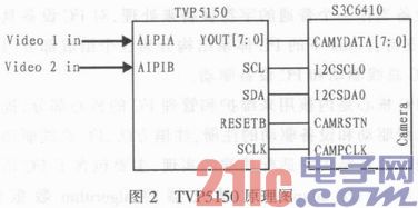
TVP5150 is an ultra-low-power high-performance video decoder introduced by TI. It can automatically identify, switch and set corresponding registers for NTSC/PAL/SECAM signals. The optimized structure of TVP5150 decoder makes it work normally. It consumes only 115 mW and is widely used in portable, high-volume, high-performance and high-quality video products. The TVP5150 decoder has an analog input channel that can accept 1 S-VIDEO signal or 2 composite video signals (CVBS). The image captured by the infrared CCD camera outputs PAL image data to the TVP5150 at a rate of 25 frames per second. The TVP5150 automatically recognizes the input PAL signal and performs A/D conversion to convert to an 8-bit digital YCbCr4:2:2 signal conforming to the ITU-R BT.656 standard. ITU-R BT.656 is the digital interface standard in Annex A of ITU-R BT.601, ITU-R BT.656 outputs 8-bit Y:Cb:Cr=4:2:2 data format, and the synchronization signal is embedded in The serial output in the data stream can also be output in parallel with the data stream on separate pins. The TVP5150 can output an 8-bit 4:2:2 ITU-R BT.656 signal or an 8-bit 4:2:2 ITU-R BT.601 signal, which is consistent with the input signal format of the S3C6410 Camera module. The conversion saves a lot of work. The TVP5150 decoder contains multiple special function registers. It can be programmed to use the I2C serial interface. The user sets the internal register of the external video decoder chip TVP5150 through the I2C bus to set the working state. The schematic diagram of the TVP5150 chip is shown in Figure 2.
2 drive design
The system driver mainly includes two parts: the camera interface driver of the processor S3C6410 and the TVP5150 driver of the video decoder. The Camera interface driver provides the underlying support for the upper layer application and follows the V4L2 standard. The video decoder TVP5150 driver completes the registration of the I2C device, follows the I2C communication protocol, and implements the interface function for reading and writing internal registers.
2.1 Camera interface driver
V4L2 (Video For TWO) is an API interface for video devices in the Linux kernel. It is mainly used to switch, collect, and output video devices. In the embedded system, Linux is used as its software platform. V4L2 is the kernel driver model adopted by Linux2.6, which is very different from the previous version of V4L. V4L2 enables the development of video device drivers under Linux with a uniform interface specification that provides clear models and interfaces for driver development. The application is at the top and the hardware is at the bottom, and the set is in the middle. Prior to the Linux 2.6 release, this specification was V4L, which put all of the video device drivers in its management, reducing the amount of work for programmers.
This program uses Linux as the operating system, and the kernel version is 3.0.1. Compared with the previous linux2.6.28, the kernel version has been upgraded. The upgraded linux 3.0.1 version is compatible with more hardware, and the previous system is fixed. The security of the bug and certain resources has significantly improved the system security performance. Camera interface driver is completed according to the V4L2 standard. The s3c_time_core.c file implements device registration and most system calls. It is the core of the driver. The ioctl system call of the v4l2 interface relies on s3c_time_v4l2.c.
In the Linux operating system, devices are mapped to special files. The device driver provides a consistent access interface for various devices. The application accesses the device by calling functions such as open, close, rea d, and write to access the device. . The open() function is used to open the video file device; the underlying read and write of the camera interface is implemented with read() and write(); mmap() replaces the previous copy_to_user() method, and maps the device memory to the application using memory mapping. In memory, the device memory is directly processed; when video_device is configured, registration is done in the s3c_time_probe() via the video_register_device() function.
2.2 TVP5150 driver
2.2.1 I2C driver architecture under Linux
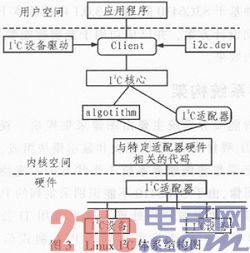
The I2C bus is a new bus standard widely used in the field of microelectronic communication control developed by PHILIPS. It is used to connect a microcontroller and its peripheral devices. Its main features are simplicity and effectiveness. The Linux system treats the I2C device as a normal character device and has good support for the I2C device. The I2C architecture under Linux is divided into three components: the I2C core, the I2C bus driver, and the I2C device driver.
The I2C core is the core part of the kernel used to maintain and manage I2C. It provides the registration and deregistration methods of I2C bus driver and device driver. The I2C bus driver is the implementation of the adapter side in the I2C hardware architecture, mainly including the I2C adapter data structure i2c_adapter. The algorithm data structure i2c_algorithm of the I2C adapter and a function that controls the I2C adapter to generate communication signals. The I2C device driver is an implementation of the device side in the I2C hardware architecture. The device is typically attached to the CPU-controlled I2C adapter and exchanges data with the CPU through the I2C adapter. The I 2C device driver mainly includes the data structures i2c_driver and i2c_client, and we need to implement the member functions according to the specific device. The Linux I2C architecture diagram is shown in Figure 3.
2.2.2 TVP5150 driver implementation
Compared with linux2.6.28, Linux3.0.1 has some changes in the driver function interface. The driver is optimized. The TVP5150 driver is implemented as follows: The TVP5150 driver must first implement the interface to the I2C core layer to mount the I2C adapter layer. To implement specific access methods for I2C bus and I2C devices, including the need to write interface functions such as TVP5150_init(), TVP5150_probe(), TVP5150_remove().
The tvp5150_init() initialization function mainly calls i2C_add_driver(&tvp5150_i2c_driver) to add a device driver.
Tvp5150_probe() is called when registering with i2C_add_driver() to check whether all discovered I2C adapters meet the specific conditions of the I2C driver. If the conditions are met, the connection is made and the I2C bus is used to implement the I2C bus and I2C. Access to the device.
Tvp5150_remove() is called when the Tvp5150 is removed, leaving the Tvp5150 decoder out of the I2C adapter and clearing the data structure describing the device.
The driver of this article mainly implements the following links:
Firstly, the structure that fills the camera interface is added: static struct s3c_fimc_camera tvp5150_da-ta. The structure mainly describes the parameters of the camera, such as image size 720x240, image format ITU_656_YCBCR422_8BIT, pixel frequency 27 MHz and so on. This data is used when initializing the camera interface. In the tvp5150_probe(struct i2c_client*c, const structi2c_device_id*id) function, a function interface s-3c_fime_register_camera(&tvp5150_data) is added to fill the above structure into the global variable struct s3c_fimc_config s3c_fimc, and then define the tvp5150 driver configuration parameter. The structure tvp5150_i2c_driver, in the tvp5150_in it() function, calls i2c_add_driver(&tvp5150_i2c_driver) to add the driver. After tvp5150_probe() is called, tvp5150_attach_adapter() will be called to detect Tvp5150 by traversing all I2C bus drivers in the system, and then call the kernel. An already registered adapter to connect to the Tvp5150. The tvp5-150_attach_adapter() function mainly calls the i2c_detect(adapter,driver) function to detect the device. After detecting the target device, it creates a strnct i2c_client structure to identify the device.
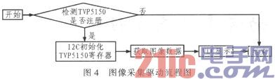
The operation of initializing the Tvp5150 internal special function register is mainly realized by the tvp5150_probe() function. The function calls i2c_smbus_write_byte_data(c, TVP5150 _init_reg[i].subaddr, TVP5150_init_reg[i].value) to complete the register setting, thus completing the initialization tvp5150. the process of. The image acquisition drive flow chart is shown in Figure 4.
3 drive transplantation and related experimental results
1) After the driver is written, add the compile configuration options for the project corresponding to the driver in the Kconfig-camera file:
Config TVP5150
Bool "TVP5150"
Depends on VIDEO_FIMC
---help---
LYT TVP5150 camera module support
2) Add a compilation entry for the driver in the Makefile:
Obj-$(CONFIG_TVP5150)+=tvp5150.o
3) Modify the mach-smdk6410.c file:
Add {I2C_BOARD_INFO("tvp51 50", 0x5c),} after the statement in the i2c_board_info i2c_devs0[]_initdata structure {I2C_BOARD_INFO("ov965x", 0x30),},
4) Enter the linux-3.0.1 kernel directory and execute make menuconfig for related configuration:
Among them External Camera (TVP5150) ->
Select 0 in the selection box in front of ResetType (0=low, 1=high)
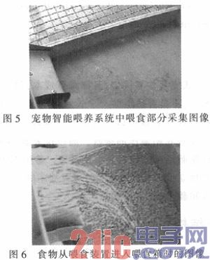
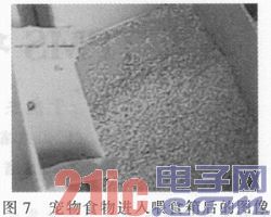
5) Enter the kernel directory to execute make zImage, re-edit the kernel, generate the kernel file, burn the new kernel to the development board, and run the test program to test the real-time image collected by the video device, as shown in Figure 5-7. .
4 Conclusion
The driver design of the pet intelligent feeding system video capture is introduced in detail through the development example. The design of TI's video decoding chip TVP5150 driver is realized and successfully transplanted to the development board. It has high cost performance and can be used for video capture and remote monitoring. In many fields, the realization of the video surveillance of the system satisfies the need for remote real-time viewing of pet feeding and activities, and provides assistance for the further improvement of the pet care system. In actual tests, the system test results are satisfactory and achieved Pet remote timing and quantitative feeding, the system has low cost and has good application and promotion value.
In-ear Wired Earphones, they are small and comfortable and simple, fit in just about any pocket,and they provide great sound that literally goes straight into your ears,bring it on your next commute or run, or simply enjoy it in the comfort of your time.
In-ear Wired Earphones
Earbuds With Removable Cable,Earphones With Replaceable Cabl,Stereo In-Ear Earphones,In-Ear Wired Headphones
Dongguang Vowsound Electronics Co., Ltd. , https://www.vowsound.com