TTL Non-Gate Circuit: Structure and Working Principle
1. Circuit Structure Diagram
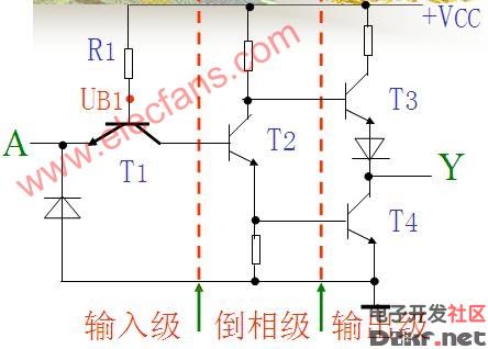
2. Working Principle
Let’s assume Vcc = 5V, UIH = 3.4V, UIL = 0.2V, and the forward voltage of the PN junction is 0.7V.
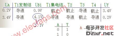
3. Truth Tables and Logical Symbols
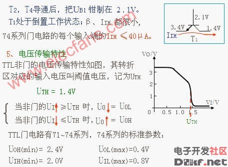
Understanding the TTL non-gate circuit requires a comprehensive grasp of its structure and operational mechanism. This type of circuit plays a crucial role in digital electronics, serving as the foundation for many integrated circuits and microprocessors. The TTL (Transistor-Transistor Logic) family has been widely used due to its high speed, reliability, and ease of implementation. In this context, the circuit operates by utilizing the properties of transistors and diodes to achieve switching and amplification functions. By carefully analyzing the provided diagrams, one can observe how the circuit transitions between different states based on input voltages. For instance, when the input voltage exceeds the threshold (0.7V), the transistor turns on, allowing current flow and signaling an active state. Conversely, if the voltage drops below this threshold, the transistor switches off, indicating an inactive state. These principles form the backbone of digital logic, enabling complex systems to process information efficiently. Additionally, the truth table highlights the binary nature of TTL circuits, where inputs yield either a high (1) or low (0) output, depending on their values. Such functionality is essential for building logic gates, flip-flops, and other fundamental components of modern electronic devices.
Industrial Barcode Scanner,Industrial Barcode Reader,Industrial Qr Code Scanner,Industrial Handheld Barcode Scanner
Guangzhou Winson Information Technology Co., Ltd. , https://www.barcodescanner-2d.com