The mixed-signal oscilloscope made its debut in 1993, featuring two analog channels alongside eight or sixteen digital ones. Over the years, the mainstream mixed-signal oscilloscope (MSO) became an indispensable debugging tool for embedded system designers. Traditionally, the number of channels has settled into a pattern: two or four analog channels paired with sixteen digital channels. Engineers favor MSOs because they allow viewing two or four signals simultaneously while scaling up to twenty signals without needing to resort to a logic analyzer.
Despite the widespread acceptance of these channel configurations, one must ask if they remain relevant for today's embedded systems. This question is crucial for both oscilloscope manufacturers and engineers designing embedded systems. Manufacturers need to ensure their products provide functionalities customers truly value, while engineers require tools tailored to their specific needs.
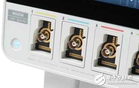
This query has inspired numerous research initiatives, with embedded system engineers worldwide delving deeper into the ideal number of oscilloscope channels. The latest 5-series MSOs reflect these studies by offering six to eight analog channels and eight to sixty-four digital channels. Additionally, the digital channels can now be reconfigured during operation.
Historically, the four-channel MSO has performed exceptionally well, suggesting that the conventional number of analog and digital channels adequately meets the needs of most embedded designers. Specifically, many engineers find four channels sufficient. However, a significant portion (35% of our research) claims they need eight analog channels.
In the past, when engineers required more than four analog inputs, they often used two oscilloscopes simultaneously. Known as "cascading," this approach presents several challenges. Synchronizing multiple oscilloscopes requires precise triggering and compatible cables or probes. Comparing data across two displays is cumbersome, leading many engineers to manually combine data from both oscilloscopes on a computer. Even with identical models, achieving synchronization can be time-consuming, and using different models complicates matters further.
Regarding digital channels, reducing the number is equally important as increasing it. Many engineers express frustration over being forced to purchase sixteen digital channels when only eight are needed. Our study reveals that about 75% of respondents prefer fewer than sixteen digital channels, with some wanting more.
Flexibility is a key requirement for embedded system designers, surpassing the number of channels in many oscilloscope features. Our research indicates that 79% of embedded engineers desire oscilloscopes adaptable to future needs, offering multiple functions to address the demands of high-pressure design teams.
When discussing system-level debugging stages, engineers often highlight the need for additional channels and flexibility during the integration of multiple subsystems. Today’s complex systems involve multiple processors, power supplies, serial buses, and I/O devices, making system-level visibility essential. Traditional oscilloscope methods require engineers to capture data multiple times using two or four channels, tracing signal paths to identify issues. Modern systems handle inputs from numerous sensors, drive multiple actuators, and communicate via multiple buses, making traditional methods increasingly problematic. These systems, integrating sensors, accelerators, processing power, and communication, form intelligent devices within the expanding IoT ecosystem.
Another challenge arises from the proliferation of power supplies in modern systems. To optimize power consumption, performance, and speed, even simple systems might include a 12V main supply, multiple 5V supplies, a 3.3V supply, and a 1.8V supply. Verifying and commissioning power-on/off sequences of these supplies, particularly concerning other control or status signals, necessitates more channels and extensive testing.
Some innovative engineers use the digital MSO channel’s variable threshold to verify power sequences. By setting the digital channel threshold slightly below the nominal voltage, they create a "timing diagram" of the power supply, reset line, interrupt, and status lines. While this method works, it overlooks the analog characteristics of the signal, which most engineers prefer to analyze using analog channels.
For many applications, a standard configuration of four analog channels and sixteen digital channels suffices. However, encountering new problems—inevitable in technology—is best met with options beyond the traditional setup.
While the four-channel MSO remains effective, the industry is evolving toward more flexible solutions, allowing engineers to adapt to emerging challenges with confidence.
Shenzhen ChengRong Technology Co.,Ltd. , https://www.laptopstandsupplier.com