Abstract: To meet the high precision acquisition of data under certain harsh experimental environment conditions. Mass storage for post-analysis needs, designed with MSP430F1611 microcontroller as the main control unit, using 16-bit high-precision A/D conversion chip ADS1146 to achieve data acquisition; using large-capacity TF memory card to achieve massive storage of data, and through the parallel port The USB chip and the corresponding PC software implement data upload for post-mortem analysis. At present, the data acquisition and storage system has been applied in relevant experimental projects, and has obtained good and stable experimental results.
0 Preface
With the development of information technology, especially the processing speed of various digital processing devices, it has become a reality to realize massive real-time data processing. However, in some harsh experimental environment conditions, data cannot be processed in real time, and the method of storage testing is still needed.
Storage test refers to the built-in micro-storage test system in the test object without affecting or affecting the measured object. The data acquisition and storage are completed in real time on the site, and the memory is recovered afterwards, and processed and reproduced by the host computer. A dynamic testing technique for measured information.
According to the specific situation, this paper designs a high-precision massive data acquisition and storage system based on MSP430F1611 microcontroller. The system adopts MSP430F1611 single-chip microcomputer as the main control unit, adopts 16-bit high-precision A/D conversion chip ADS1146 and 2 GB capacity TF memory card to realize high-precision data acquisition and specified block storage; the host computer and the single-chip microcomputer pass the parallel port to USB The chip FT245 is connected, in which the reading of the block data specified by the TF memory card and the erasing operation of the block data are performed by using Lab-
The upper computer program written by VIEW is completed. Therefore, the user can easily and conveniently complete the collection, storage and post-processing of massive high-precision data in some harsh experimental environments. At the same time, the system has a large capacity. High precision. Low power consumption and small size.
1 system design
1.1 MCU basic system
The basic system of the single chip microcomputer is the core of the entire control system, which completes the signal processing and coordinated control of the entire system. Its structural block diagram is shown in Figure 1. Its main work is to perform initialization after power-on, set the sampling period, start the A/D sampling circuit, read the sampling data, and temporarily store it in its own RAM storage area. When the stored data reaches a certain amount, it is stored in the specified TF memory card data block; after the data acquisition and storage is completed, the single chip microcomputer is connected with the upper computer, and when the TF memory card block data sent by the upper computer is received, the data is read. When the command is sent, the corresponding block data is uploaded to the host computer and stored as a specified type of steering file. In addition, when the host computer sends a TF memory card erase command to the MCU, a confirmation dialog box for confirming the erase of the specified block will pop up on the user interface to determine again. Blocks to be wiped out to prevent accidental erasure.
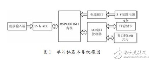
The system center control unit selects the 16-bit low-power single-chip MSP430F1611[5] produced by TI. The chip operates from a voltage range of 1.8 to 3.6 V, has 48 KB + 256 B of FLASH MEMORY and 10 KB of RAM, and a rich set of on-chip peripherals such as Timer A, B (TImer A, TImer B), 48 programmable I/O, as well as serial port 0, 1 (UART0, 1), so it can better meet system design requirements.
1.2 A/D sampling circuit
The 16-bit high-precision A/D conversion chip ADS1146 is selected, and its connection circuit with the single chip microcomputer is shown in Fig. 2.

The ADS1146 and the MCU are selected as the three-wire SPI communication mode, that is, the P3.1~P3.3 pin of the MCU is selected as the second function: SIMO0, SOMI0 and UCLK0, and the data transfer rate and the programmable gain amplifier are set by initializing the corresponding registers. The gain value can be programmed to detect whether the P3.1 pin is low. If it is low, write 0001 001X to the U0TXBUF register of the microcontroller, start the single read RDATA mode, and then write two to the microcontroller U0TXBUF. The NOP instruction simultaneously puts the U0RXBUF high byte data MSB obtained by the operation of the single chip into the upper 8 bits of the previously defined integer data, and puts the low byte data LSB into the lower 8 bits of the integer data.
1.3 TF memory card
The role of the TF memory card is mainly to store data. The specific implementation process is: reading A/D sampling data, and temporarily storing it in the RAM storage area of ​​the single chip microcomputer, and storing the stored data into the designated TF memory card data block when the stored data reaches a certain amount, thereby reciprocating Until the storage of the predetermined data block of the TF memory card is completed. This system adopts TF memory card produced by SanDisk with 2 GB capacity. It is especially suitable for data acquisition and storage system with large capacity data storage requirements. The connection circuit between TF memory card and MSP430F1611 is shown in Figure 3.
The TF memory card has a volume of 15 mm & TImes; 11 mm × 1 mm, which is equivalent to the size of the fingernail cover, and includes two bus modes, SD protocol and SPI protocol. The system bus mode is set to SPI mode by the COM0 command. Set the corresponding control register of the microcontroller UART and select the second function SIMO1, SOMI1 and UCLK1 of the P5.1~P5.3 pin, in addition to the TF memory card initialization. Single block read. The single block write and erase operations are performed by calling the COM1, COM17, COM24, and COM38 instructions and their corresponding steps, respectively.
1.4 Communicating with the host computer
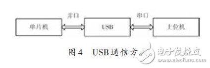
FT245 is a parallel FIFO bidirectional data transmission USB chip of FTDI. The USB communication mode in this system is shown in Figure 4. The FT245 provides 8-bit parallel data bus D0~D7 to the MSP430F1611 microcontroller, and installs VCP driver on the host computer. The program converts it to a virtual serial port.
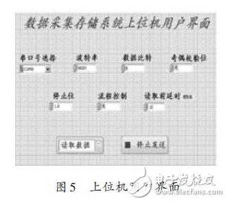
The PC software is developed based on LabVIEW's VISA (Virtual In-strument Software Architecture) interface module. VISA is a standard I/O application interface for instrument programming. It is a common instrument driver standard application interface (API) in the industry. ), using object-oriented programming, with good compatibility. Scalability and independence [10-11]? The user interface of the host computer developed by using it is shown in Figure 5. After the data acquisition and storage is completed, the data read function can be selected. At this time, the MCU will read the data stored in the corresponding block in the TF memory card and send it serially. The upper computer is saved as a steering file. Txt for post-mortem analysis of the data.
2 Conclusion
The system solves the problem of high-precision data mass storage for post-mortem analysis under certain harsh experimental environment conditions. In addition, after the data acquisition and storage is completed, the user can read the data command through the host computer software to obtain the data stored in the corresponding block in the TF memory card. The txt document can be further analyzed by calling Matlab. At the same time, the system has a small size. The advantage of low power consumption.
Road Traffic Signs are graphical symbols that display traffic regulations and road information. They can make traffic regulations visually, concisely and concisely expressed. At the same time, they also express the content that is difficult to describe in words. They are used to manage traffic and indicate the direction of driving to ensure the smooth flow of roads and the safety of driving. Applicable to highways, urban roads and all special highways, with the nature of the law, vehicles, pedestrians must comply with.
Road Traffic Signs
Road Traffic Signs,Traffic Light Sign,Road Safety Signs,Highway Road Traffic Signs
Yangzhou Heli Photoelectric Co., Ltd. , https://www.heli-eee.com