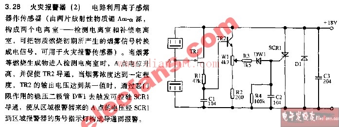
This section provides an overview of the circuit diagram for a fire alarm system, specifically focusing on a three-schematic design. These diagrams are essential for understanding how the various components interact in a fire detection and alarm setup.
The first image shows a general fire alarm circuit diagram, which illustrates the core layout of the system. It includes elements like sensors, control units, and alarm indicators that work together to detect smoke or heat and trigger an alert.

Next, we have a detailed view of the three schematic diagrams that make up the complete fire alarm system. Each schematic represents a different part of the circuit, such as the power supply, signal processing, and output stages.


These schematics are particularly useful for engineers and technicians who need to troubleshoot or modify the system. They provide a clear visual guide to the wiring and component placement, making it easier to understand the flow of signals and power within the circuit.
If you're working with fire alarm systems or studying electronics, these diagrams can serve as valuable references. Whether you're designing your own system or analyzing an existing one, having access to detailed schematics is crucial for accurate implementation and maintenance.
stainless steel antenna,stainless steel whip antenna,metal cb antenna,stainless steel cb antenna
Mianyang Ouxun Information Industry Co., Ltd , https://www.ouxunantenna.com