The A44 Hall effect sensor is a widely used component in various electronic applications due to its high sensitivity and reliability. Below is the pin diagram for the A44 Hall sensor, which helps users understand how to correctly connect it to their circuits.
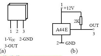
Figure 12: Pin Diagram of the A44E Integrated Switch-Type Hall Sensor
 As you can see from the diagrams above, the A44 Hall sensor has three main pins: VCC (power supply), GND (ground), and OUT (output signal). This configuration allows the sensor to detect changes in magnetic fields and convert them into digital signals that can be read by microcontrollers or other electronic devices.
Smart Multimeter ,Smart Digital Multimeter,Digital Smart Multimeter,Multimeter Smart
YINTE TOOLS (NINGBO) CO., LTD , https://www.yinte-tools.com