The power factor requirements of LED bulbs are becoming stricter in various countries, and the design challenges of LED drive circuits are increasing. Therefore, by improving the buck topology, semiconductor manufacturers have developed a new generation of LED drive solutions that can take into account the requirements of small size, high energy efficiency, and high power factor. , Help developers to design LED bulbs with power factor above 0.9.
With the gradual elimination of incandescent light bulbs, energy-saving fluorescent lamps (CFL) and light-emitting diodes (LED) will become two lighting options that provide significant energy-saving effects. Despite the maturity of CFL technology, white LEDs have developed rapidly, and the output lumens and luminous efficiency of each LED element have become higher and higher. The service life of LED bulbs is more than 25 times that of standard incandescent bulbs, and the light efficiency has exceeded the performance level of CFL bulbs.
The electronic ballasts in most common CFL bulbs are capacitive, with a typical power factor (PF) of 0.5 to 0.6. This means that although households pay only for the power indicated by the light bulb, the power company must actually produce a proportional amount of volt-amp (Volt-amp) power, so a 13-watt CFL bulb with a power factor of 0.5 represents 26 volts- The load is only slightly lower than 50% of the 60-watt incandescent bulb volt-ampere.
Therefore, the US Energy Star stipulates that the minimum power factor of LED bulbs with a power greater than 5 watts must be 0.7, and the minimum power factor of commercial LED lamps such as recessed lights and spotlights must be 0.9. Looking at the world, the United States does not have the strictest power factor requirements for LED bulbs; the most stringent is South Korea. The country requires a minimum power factor of 0.9 for all lights with an input power of more than 5 watts. This requirement will be used to design LED driver circuits. Designers pose challenges. They must comprehensively evaluate energy efficiency, available space, and overall bill of materials (BOM) costs to provide optimized LED lighting solutions.
Introduce buck topology circuit LED bulb PF great leap forward
Incandescent bulbs are only designed for the voltage of a specific line; but designers do not need to consider how to make a universally designed LED bulb popular around the world. In addition, the power supply in the LED bulb does not need to be electrically isolated from the load because it is integrated in a single housing (Housing); however, it must still pay attention to the design of the mechanism and must meet the safety requirements physically. With this in mind, designers no longer have to rely on the isolation flyback topology as the only power conversion architecture choice.
Under certain boundary conditions, the buck topology can be optimized to provide a good power factor. To provide a high power factor, the input current must be consistent with the line and increase proportionally as the voltage of the rectified line increases. The disadvantage of the buck topology is that the current flows only after the input voltage Vin is greater than the output voltage Vout, so the LED string voltage must be lower than the line voltage. In most cases, this is not a problem because the number of series-connected LEDs is relatively small compared to the line voltage. For example, the total voltage of eight series-connected LEDs is about 25 volts, which is less than 15% of the peak rectified 120-volt AC input voltage. .
One control method for high power factor boost converters is fixed on-time control. In this control mode, when the inductance and current reach zero, a switching cycle will restart. In order to control the power, the designer must use feedback to adjust the on-time, and can use the same concept to achieve the buck topology. With a fixed on-time, the current flowing through the inductor / switch rises in direct proportion to the line, providing a near-perfect power factor. The trade-off is that the peak current at the top of the switching cycle can be extremely large. Bulb applications do not require excellent power factor; therefore, if a certain part of the peak current in the switching cycle is limited, it can reduce the loss of the switch and the inductor, provide higher conversion energy efficiency and limit the size of the inductor. The typical line current waveform generated by this method cannot be as close to a sinusoidal curve as shown in Figure 1. However, the waveform generated by this method easily provides a power factor greater than 0.9, but the trade-off is increased distortion.
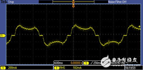
Figure 1 Input current waveform
Promote bulb PF LED controller to play a key role
In order to apply this fixed on-time / peak current hybrid mechanism, the semiconductor industry developed the NCL30002 controller (Figure 2).
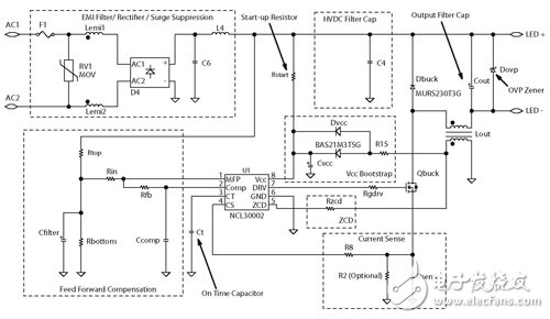
Figure 2 Power factor correction buck application circuit diagram
From the controller circuit diagram, it can be observed that the LED refers to the high-voltage rail; the power switch refers to the ground, which is called reverse buck. It simplifies the architecture. The main factor is that it can directly sense the peak LED current and drive a single-junction field-effect transistor (FET) without using a level converter.
1.Solar powered outdoor lighting with a maximum run time of 24 hours!
2.15W Led Lamp gives of a strong glow each night
3.Easy to install and requires no wiring, assembly or maintenance
4.Sets up in seconds and starts gathering power the moment its exposed to the sun
5.Over charge and discharge protection provide fail-safe mechanisms against faulty batteries
6.Has a lithium battery with an expected lifespan of 4-5 years
7. The powerful solar panels will absorb all the necessary energy during the day, for long time use at night. An over charge & discharge protection system ensures, your batteries are always protected from solar energy fluctuations. Will last for 24 hours
Solar Yard Lights,Solar Outdoor Lighting,Solar Lights For Garden,Solar Garden Lights
Yangzhou Beyond Solar Energy Co.,Ltd. , https://www.ckbsolar.com