In the process of soldering capacitors onto a printed circuit board (PCB), if the board becomes bent during handling, the capacitor could potentially be damaged or even broken. To prevent this issue, it's advisable to mount the capacitor in the opposite direction of the board's curvature. This article will explain how to properly orient components to reduce stress caused by board warping or bending.
1) **Circuit Board Pressing Direction and Component Mounting Orientation**
Figure 1 illustrates an example of how components can be mounted in either a longitudinal or lateral direction depending on the pressure applied to the board. When facing the direction of the pressure, mounting components laterally helps to distribute the force more evenly across the board, reducing the risk of damage.
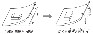
The results of testing the bending resistance of the board are shown in Figure 2. It is clear that when components are mounted in two different directions, the board’s resistance to bending increases significantly, making it less likely for pressure to affect the components directly.

2) **Capacitor Installation Near Cracks on the Board**
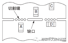
Cracks or cutouts on a PCB can create high voltage points during the manufacturing process. For example, when assembling components near a crack, as shown in Figure 3, the order in which parts are placed can influence how much pressure they experience.
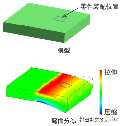
To better understand the impact of such cracks, we examined the board’s deformation when there was no gap. The finite element method (FEM) analysis results are shown in Figures 4 and 5. Imagine a scenario where a component is mounted at a specific location on a 1.6mm thick FR4 PCB.
Figure 4 shows the case without any gap. In this situation, the board experiences significant pressure, leading to red-yellow tensile stress at the mounting point, which may cause the capacitor to crack. However, in Figure 5, where a notch is present, the board shows minimal bending. The stress is reduced, and the component experiences less pressure, making this an effective way to prevent capacitor cracking.

In summary, adding a notch can help relieve pressure on the board. The most effective approach is to align the component parallel to the notch (as seen in position D in Figure 3). If the component orientation cannot be changed, it's recommended to add a notch to minimize board deformation (position B in Figure 3). These strategies can significantly improve the reliability of the PCB assembly process.
Longhua Manxueling Trading Company , https://www.mxlvape.com