In the process of soldering a capacitor onto a circuit board, if the board becomes bent during handling, it can lead to the capacitor being damaged. To prevent this, it's advisable to install the capacitor in the opposite direction of the board’s curvature. This article explains how to position components in a way that reduces stress caused by board warping or bending.
1) **Circuit Board Pressing Direction and Component Mounting Orientation**
Figure 1 illustrates the optimal orientation for mounting components based on the direction of pressure applied to the board. When components are mounted laterally relative to the direction of pressure, it helps to distribute the force more evenly across the board.
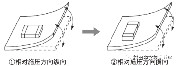
The results of testing shown in Figure 2 demonstrate that mounting components in specific directions improves the board’s resistance to bending. This makes it harder for pressure to be transferred directly to the components.

2) **Capacitor Installation Near Cracks on the Board**
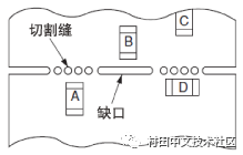
Cracks or cutouts on a circuit board can cause electrical issues during production. For example, when installing components near a crack, as shown in Figure 3, the order in which parts are assembled can affect their vulnerability to pressure.
To better understand the impact of no gaps, we analyzed the board’s deformation using FEM (Finite Element Method). The analysis was conducted on a 1.6mm thick FR4 board.
Figure 4 shows the scenario without any gap. In this case, high pressure is applied to the board, causing red-yellow tensile stress at the component mounting area, which could potentially crack the capacitor.
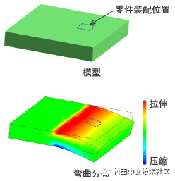
On the other hand, Figure 5 presents a model with a notch. Here, the component is positioned in green, and the board experiences minimal bending. The pressure on the component is significantly reduced, making this an effective method to prevent capacitor cracking. In summary, adding a notch helps relieve pressure, and the most effective approach is to align the component parallel to the notch (as shown in D of Figure 3). If the component orientation cannot be changed, it is recommended to create a notch to reduce board deformation (as shown in B of Figure 3).

Airmez
Longhua Manxueling Trading Company , https://www.mxlvape.com