Some irrevocable operations (such as releasing a parachute, cutting a rope, or starting a solid flammable missile engine) can be performed by a pyrotechnic igniter. Such devices typically consist of an electrically controlled igniter, some chemicals for generating high pressure gas after ignition, and a mechanical assembly that performs the desired operation.
This article refers to the address: http://
The flammable mixture of the igniter contains a filament. When current is passed through the filament, the temperature is lowered until the combustion temperature of the combustible chemical is reached, thereby igniting the device.
The characteristics of the igniter are typically described by the filament resistance (eg 1OΩ) and the energy supplied to the starting device over a maximum time (ie milliseconds). Another parameter that is often assigned is the maximum current that can be safely supplied to the device without ignition. The key considerations for operating such a device with an MCU are as follows:
Avoid unnecessary operations (that is, some unpredictable port conditions that may trigger the device at startup);
Should be able to use the same port to check the device situation;
Current (high), energy, and device timing requirements are met without disrupting electronics.
Figure 1 is a block diagram of the fire extinguisher interface. The current through the filament is controlled by the power MOSFET (Q1). The Q1 gate is controlled by a charge pump connected to the MCU port via C1, which avoids: unnecessary port-level operation Q1 (DC part is isolated by C1); single spike voltage operation Q1 (based on charge pump characteristics, several conversions are required) To improve the door level); the power supply through the filament affects the power supply (C2 is selected to provide the right amount of energy to the filament and slowly charge through R2).
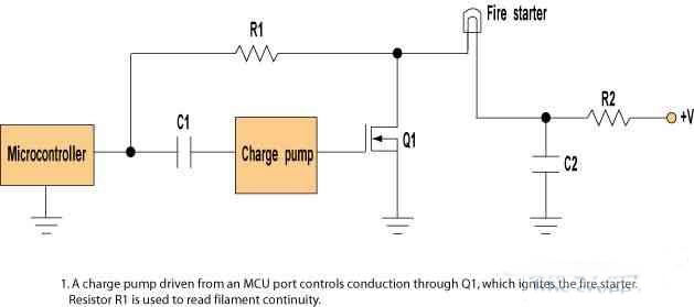
Figure 2 is a schematic diagram of the working circuit required to accomplish the following. The charge pump drives the power MOSFET (M1), which requires several transitions at the MCU port to saturate M1. In this way, the system's response to spikes and unnecessary changes in intensity is slow.

By looking at the filament resistance, you can understand the condition of the igniter. R4 and R5 make the MCU port (used as an input) close to +5 V through a lossless filament, while the MCU port is close to 0 V through a burnt-out filament.
M1 discharges the charge of capacitor C6 through the filament to provide the required energy. The igniter used (Daveyfire N28BR) ignited a minimum of 2 ms /1 A (or 1.1 mJ/O). The microprocessor port is considered an input when no vibration is transmitted. The stronger signal returns before the pulse (the igniter is new) and the weaker signal returns after the igniter burns out. This circuit goes far beyond the minimum requirements for current and energy/resistance required to ignite the Daveyfire igniter.
Install on Auto/Aircraft, Auto Signal, Recreation Vehicles, Trucks/ Trailers, Marine/ Boats,Motorbikes etc.
Be used as Direction light, emergency vehicle lamp, dashboard light, Dash light, instrument light, indicator light, stop lamp, brake light, tail Lamp, side lamp, parking lamp, tag lamp, license plate light, turn signal lamp, dome lights, interior lighting, warning indicator, etc.
Yacenter has experienced QC to check the products in each process, from developing samples to bulk, to make sure the best quality of goods. Timely communication with customers is so important during our cooperation.
If you can't find the exact product you need in the pictures,please don't go away.Just contact me freely or send your sample and drawing to us.We will reply you as soon as possible.
Brake Light Wiring,Brake Light Wiring Harness,Brake Light Harness,Christmas Light Wire Harness
Dongguan YAC Electric Co,. LTD. , https://www.yacenter-cn.com