Op-amp circuits are typically designed for standard operational amplifiers that operate with voltage inputs and voltage outputs. However, another type of op-amp is widely used in audio processing applications: the transconductance operational amplifier (OTA). Unlike traditional op-amps, OTAs have a voltage input and a current output, making them ideal for applications where gain control is essential. The gain in an OTA is determined by an external bias current, which allows for dynamic adjustment of performance characteristics.
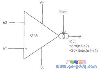
The figure above illustrates the circuit symbol of an OTA along with its fundamental working principle. The differential input receives two signals, e1 and e2, and the output current is the difference between these two signals multiplied by the transconductance (gm) of the OTA. Transconductance is measured in Siemens (S), where 1 S equals 1 Ωâ»Â¹. The value of gm is proportional to the external bias current (Ibias), specifically, gm = 20 × Ibias. This means that by adjusting the bias current, the gain of the OTA can be easily controlled. In practical use, the bias current can vary over a range of up to 1000:1, offering great flexibility in circuit design.
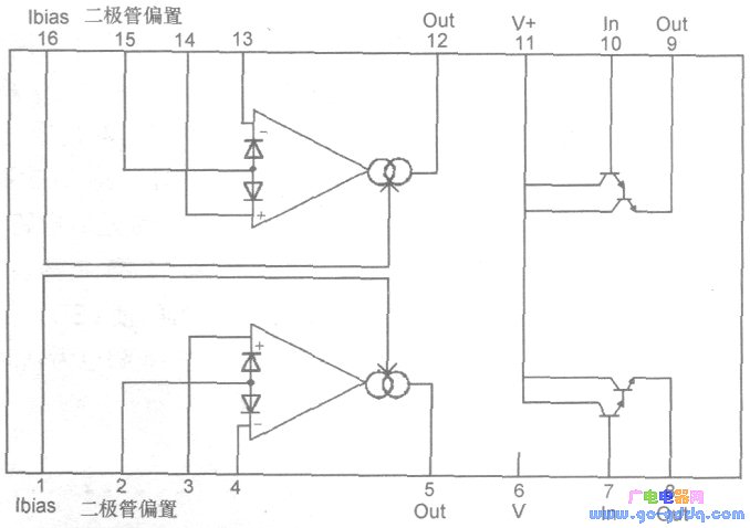
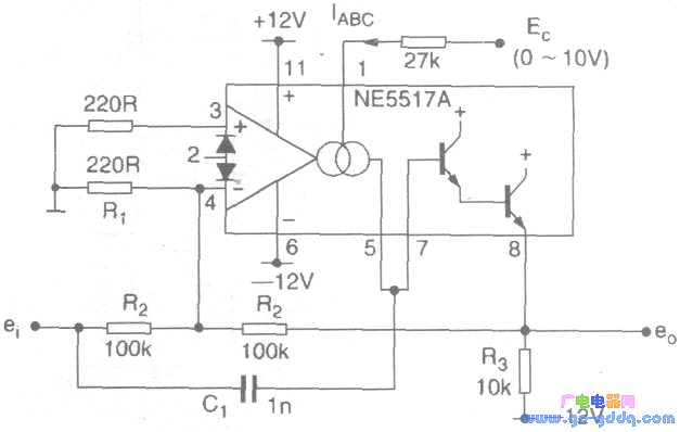
The image shows the pin configuration and internal circuitry of the NE5517, a commonly used OTA IC. Figure 3 demonstrates a ring modulator circuit built using the NE5517. In this setup, the carrier signal is applied through resistor R2 and then output via R3. The modulation voltage is fed into pin 1 of the NE5517. When the modulation voltage is positive, the OTA's gain increases, causing the output current from the OTA to exceed the direct input current through R2, resulting in an inverted carrier signal. Conversely, when the modulation voltage is negative, the OTA gain decreases, allowing the direct input current through R2 to dominate, producing an in-phase carrier output.
Adss Fiber Optic Cable,adss cable,cable adss,Singlemode Adss Fibre Optics,Adss Fiber Cable
Guangzhou Jiqian Fiber Optic Cable Co.,ltd , https://www.jqopticcable.com