 The following is the circuit diagram of [JRC4558 working principle and circuit]
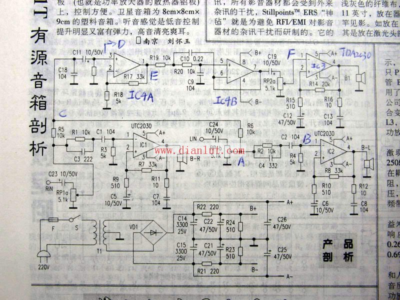
The working principle, as shown in the picture: is mainly divided into three parts. 1. Power circuit, satellite box power amplifier circuit, subwoofer circuit.
First, the power circuit (the bottom part of the drawing): 220V mains through the fuse (F), and switch S into the transformer primary, the secondary output of the transformer double 12V AC, dual 12V into the bridge rectifier composed of VD1 The circuit circuit, after bridge rectification and C14, C15 (3300UF/25V) filtering, the output no-load voltage is about plus or minus 16V (root number 2 times 12V), that is, A+ is positive 16V, A- is negative 16V. The positive and negative 16V is the power supply for the three power amplifier chips TDA2030 and UTC2030. After the other step is stepped down by R21 and R22, the power supply voltage is supplied to the bass preamplifier and the low pass filter IC4 by the B+ and B- outputs of approximately plus or minus 12V.
In this drawing, the preamplifier power supply does not use the 78/7912 three-terminal regulator circuit. When the mill enthusiasts replace two 3300UF capacitors, they can also consider adding the LM7812/7912 to provide more stable work for the front. Voltage.
Second, the left and right channel amplification circuit (satellite box power amplifier circuit), because the left and right channels are completely consistent. Here I only use the left channel of the drawing as an example to give an introduction. As shown in the figure: RIN is the signal input terminal, and enters the volume potentiometer through the coupling capacitor C23. (The volume potentiometer consists of three pins. The input terminal is connected to C23, the output terminal is also called the sliding terminal, and the other pin is the ground terminal. After adjusting the volume, the signal enters the treble boost circuit consisting of R1/C3, which can boost a certain amount of high-frequency signals to make the sound clearer. Afterwards, the signal enters the left channel power amplifier through the coupling capacitor C1. The model is UTC2030's 1 pin. After power amplification, it is output by the fourth pin of 2030 to push the satellite box to sound. R7 in the figure is the feedback resistor, and R7/R9 is the amplification factor that determines the 2030 chip. Therefore, by adjusting the resistance of R7, you can adjust the magnification. R11/C7 is the speaker compensation network.
Third, the subwoofer circuit. From the left and right channels through two 10K resistors R5, R6 and then to the C11 coupling capacitor, then the signal enters IC4, the model is JRC4558's 3 feet, IC4A is the subwoofer preamplifier. R201T sets the magnification of this amplifier to about 6 times. (R17/R18), after preamplification, to ensure a sufficiently large driving voltage to obtain a sufficiently large volume. The 1558 of the 4558 is the pre-output, and after R19, it enters the low-pass filter composed of IC4B, C9, C10, and R20.
The function of the low-pass filter is to cut off low-frequency signals below 200 Hz, and R20 and C10 determine the cut-off frequency. (The specific cutoff frequency setting of each manufacturer is slightly different). After IC4B output----C19, it is connected with the input end of the volume potentiometer. After adjusting the volume of the subwoofer, the output from the sliding end of the potentiometer enters the subwoofer power amplifier circuit IC3; TDA2030A, the principle of this circuit is consistent with the satellite box power amplifier . The 4 pin is the output, which pushes the woofer to sound.
The above is the basic working principle of R201T. By the way, it is pointed out that there is an error in the above figure: that the 1-pin input of TDA2030A should be marked as "+" or the non-inverting input. The 1 and 2 feet of the drawing are reversed.
Note: The chip LM1875T used in Edifier R1900TII, 1800TII. Light Cavalry V23SE, Swans M200, M20W, M20L T120. The working principle is consistent with the TDA2030A in this paper.
NEA Standards are guidelines from the National Electrical Manufacturers Association (NEA) for the design and construction of utility poles used to support power lines. These standards outline the material, size, strength and installation requirements for utility poles to ensure that they carry power infrastructure safely and reliably. Poles that meet NEA standards are typically made of wood, steel, or concrete and can withstand a variety of environmental conditions and loads.
Nea Standard Pole,Electric Power Transmission Pole,Steel Transmission Pole,Distribution Transmission Pole
JIANGSU HONGGUANG STEEL POLE CO., LTD. , https://www.hgsteelpoles.com