In people's traditional consciousness, the lighting system is only for the purpose of lighting. The main control methods in the traditional lighting system are manual control mode and automatic control mode. The manual control mode is simple and effective, but it relies too much on manual operation, and the control is relatively scattered, and cannot be effectively managed; the automatic control mode mainly implements control of the lighting device by means of a clock component, a photoelectric component or a combination of the two. Control method reduces the dependence on personnel, management phase
For concentration, automation of lighting control is achieved, but dimming control of the lighting system is not possible.
In addition, with the continuous improvement of living standards, people's demand for wireless, networking, intelligent and energy-saving of daily life is becoming more and more intense. The above two traditional lighting control systems can no longer satisfy people's quality of daily life. demand. Based on the above reasons, a design of indoor intelligent lighting system based on ZigBee and STM32 is proposed.
1 overall system design
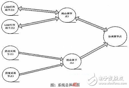
The system is mainly composed of a terminal node, a router node and a coordinator node. The three nodes perform their duties, the terminal node is mainly responsible for the transmission of messages and allows its nodes to access the network through it; the coordinator node is mainly responsible for the establishment, maintenance and management of the network, and the collection of the entire network data information, Processing and display, etc. Among the three nodes, the coordinator node is the core of the entire network. The overall design block diagram of the system is shown in Figure 1.
The main functions of this design are as follows:
(1) Using LED lamps with dimming module, the brightness of the light can be automatically adjusted through program control, and the indoor illumination is maintained in a suitable state by mutual compensation of indoor light and natural light;
(2) Using the illumination collection node, the indoor illumination can be collected and monitored in real time;
(3) Add the power-down self-locking function (in the case of sudden power failure, all the lamps are turned off again);
(4) Adding some scene modes, it is convenient to choose the lighting environment in different indoor environment requirements (such as the theater mode when the family watches TV together, the learning mode when reading and writing, etc.).
In addition to the above main functions, this design also reserves some peripheral interface circuits, you can add some corresponding sensors to achieve more functions (such as adding gas sensors to prevent kitchen gas leakage, adding smoke sensors to prevent fires, etc.)
2 system hardware circuit design
The system hardware circuit part mainly consists of four parts: the coordinator node circuit, the system illumination acquisition node circuit, the system LED dimming node circuit and the system router node circuit.
2.1 System illumination node circuit design
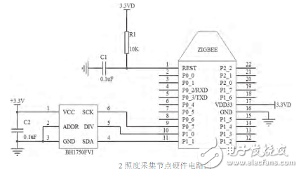
The illuminance acquisition node consists of CC2530 and illuminance sensor (BH1750FVI). The node mainly collects the indoor illuminance in real time and sends it to the coordinator through the ZigBee module. The coordinator then integrates the received illuminance information, and then displays the indoor illuminance information in real time on the LCD, and according to the illuminance information. Send corresponding commands to the LED lighting nodes to adjust the brightness of the LEDs.
The BH1750FVI sensor is a photoelectric integrated sensor, which has the following main features: 1) it can output digital values ​​corresponding to brightness; 2) a wide range of input light (equivalent to 1-65535lx); 3) low by reducing power function Currentization; 4) No other peripheral components required; 5) Low light source dependence (incandescent, fluorescent, halogen, white LED, fluorescent).
The illuminance node hardware circuit diagram is shown as in Fig. 2.
2. 2 system LED dimming node circuit design
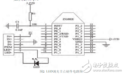
The LED dimming node consists of CC2530 and dimming module. The dimming module can adjust the brightness of the LED lamp in real time according to the instruction received by the ZigBee module. The purpose of dimming is to compensate the indoor natural light and the LED light to make the indoor illumination reach a suitable state.
The dimming module of this node selects the LED constant current driving PWM dimming module. LED dimming node hardware circuit diagram design shown in Figure 3.
2.3 System Router Node Circuit Design
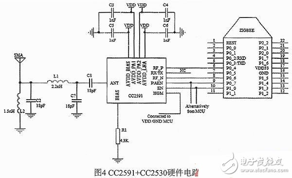
The router node is a CC2591 module that is extended on the CC2530 module. This module is a truly well-designed PA+LNA wireless transceiver module. The node is mainly responsible for receiving the terminal node information and forwarding it to the coordinator, or forwarding the feedback information of the coordinator to the terminal node.
In the open field, the transmission distance of CC2530 can reach 100m, but in the indoor environment, due to the occlusion of the wall, there is a path loss problem, and the actual transmission distance is greatly shortened. If only one routing node consisting of CC2530 is placed in the middle of the room, it is likely to cause data transmission errors or even data loss. Therefore, when actually designing the circuit, the router node adopts the form of CC2591+CC2530 combination. The CC2591 is a 2.4GHz RF front-end chip that increases transmit power through the PA to extend communication distance. The chip can also improve the sensitivity of the receiver through the LNA. Through the above two points, the integrity of the data transmission of the system can be well guaranteed. CC2591 + CC2530 hardware circuit shown in Figure 4.
2.4 System Coordinator Node Circuit Design
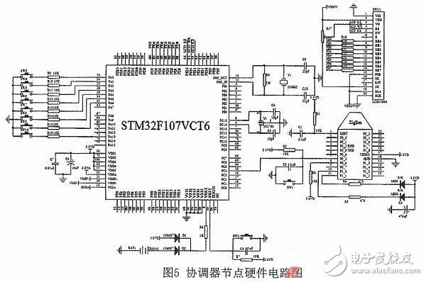
The coordinator node consists of STM32F107, CC2530, 12864LCD, matrix keyboard, DS18B20 and DS1302 modules. This node is the core of the whole system. It is mainly responsible for the establishment, maintenance, control of the joining and deletion of terminal nodes, and the processing and display of the entire system information. Among them, STM32F107 is a new STM32 interconnected microcontroller from STMicroelectronics. This chip integrates various high-performance industrial standard interfaces, and STM32 different models have perfect compatibility in pin and software, and can adapt to various applications. . In addition, the chip can also be embedded in the μC/GUI system, with independent 32-bit instruction bus and data bus, fully supporting 32-bit Thumb-2 and 16-bit Thumb instructions.
The matrix keyboard circuit adopts 2&TImes;4 matrix keyboard for time adjustment of clock and selection of different scene modes; display circuit adopts 12864 LCD, can display 4 lines of information, each line displays 16 characters, fully meets display illumination, time and Temperature and other requirements.
The schematic diagram of the hardware circuit of the coordinator node is shown in Figure 5.
3 software part design
The software part mainly completes the programming design of the whole system hardware circuit. The terminal node program mainly completes the collection, uploading and control of information. The coordinator node program is used to implement the establishment, maintenance and management of the entire network and the collection, processing and display of corresponding data. 3.1 Coordinator node software design
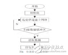
The coordinator node first determines whether there is data transmission, and if so, the selected channel establishes a network, performs data scanning and reading, and packages and transmits data. Since the power loss is mainly concentrated in the receiving and receiving phase of the wireless data, it is put to sleep before the wake-up command of the clock signal is received, so as to extend the life of the battery and reduce the power consumption. The program flow chart is shown in Figure 6.
3.2 Terminal node software design
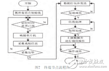
The software design of terminal node data acquisition includes two parts, which are the design of the driver of the single-chip CC2530 and the design of the sensor transceiver data. First, the module is initialized, then the timer is started, and the channel scan is performed at intervals to check whether there is a request for accessing the network. If so, first determine which sensor port is activated, and then send a data acquisition request to the port. In sleep mode, the collected data is sent to CC2530 for further processing. The program flow chart is shown in Figure 7.
3.3 Router node software design
In the program, the device type is set to the network routing node. In the ZigBee protocol stack, only the application layer event processing function needs to be changed to call the program to send the received information after receiving the information.
4 system debugging
In order to test the function of the system, the dormitory is selected as the experimental place. Three lighting nodes and one illumination collection node are placed in each of the three bedrooms of the dormitory, and then the functions of the system are tested. Through testing, the system can accurately implement wireless control functions. The illuminance node can accurately collect the illuminance information of the environment, and the ZigBee module can normally transmit the data to each other, and the PWM dimmer module can accurately adjust the corresponding brightness of the LED lamp. In addition, various scene modes, such as indoor temperature and clock information, can work normally according to predetermined indicators.
5 Conclusion
This wireless intelligent lighting system can be used not only for the automatic control of indoor lighting, but also for manual adjustment according to different needs, which can save energy and make the indoor illumination reach the best state suitable for human activities. The system has the characteristics of small size, low power consumption, strong function and flexible expansion. In addition, the system can be used not only in the home interior but also in various classrooms, company office areas, conference rooms and KTV, etc., and the corresponding modules and programs can be adjusted accordingly. This system has broad application prospects in the field of intelligent lighting control.
Microstepping is a method of controlling stepper motors, typically used to achieve higher resolution or smoother motion at low speeds.
Micro Stepper Motor divides each full step into smaller steps to help smooth out the motor`s rotation, especially at slow speeds.
Microstepping is achieved by using pulse-width modulated (PWM) voltage to control current to the motor windings. The driver sends two voltage sine waves, 90 degrees out of phase, to the motor windings. While current increases in one winding, it decreases in the other winding. This gradual transfer of current results in smoother motion and more consistent torque production than full- or half-step control.
Micro Stepper Motor
Micro stepper motor,Micro linear stepper motor,Micro stepping stepper motor
Shenzhen Maintex Intelligent Control Co., Ltd. , https://www.maintexmotor.com