Abstract: A car accident automatic positioning alarm system is designed, which uses technologies such as MEMS, GPS and GSM. Due to the moment of the car accident, the acceleration of the car body is very large, far exceeding the acceleration of the emergency braking, so the magnitude of the available acceleration is used as the basis for judging the occurrence of the car accident. The MEMS accelerometer is used to collect the signal. After the CPU process, if the acceleration value exceeds the protection value, the latitude, longitude and related information detected by the GPS will be sent to the relevant department through the GSM platform, and the rescuer can quickly rush to the scene for emergency treatment. This design provides a new way to better protect people's lives and property in special circumstances.
Key words: MEMS accelerometer; GPS positioning system; GSM communication technology; alarm
One of the goals pursued by the automotive industry is to maximize the safety of drivers and passengers in the event of an accidental collision. According to the statistics of the Ministry of Health of China, among the 1,000 injured people in traffic accidents, only 14.3% of the injured can get to the hospital in time by ambulance. Road traffic accidents indicate that if emergency rescue measures are used within 5 minutes of traffic accidents, emergency treatment within 30 mm can save at least 18% to 25% of seriously injured people; in addition, about 40% of deaths in car accidents in China The injured were killed on the spot, and the remaining 60% died on the way to the hospital or to the hospital. 30% of the injured were killed because the rescue was not timely. With the deepening of automotive safety research, the use of increasingly sophisticated vehicle collision protection systems (such as airbags) can effectively reduce the fatality of car accidents, but also has many drawbacks (such as not being able to call the police in time). This design can automatically make an emergency call after a car accident, telling the relevant department the exact location and time of the car accident, so that it can send a rescue team at the first time to rescue the wounded to gain more time and save more lives.
1 System principle and structure framework In order to improve traffic safety, the Western traffic management department has set a death acceleration of 500 g (g=10N/kg) to awaken people. This means that if the acceleration of the vehicle exceeds this value, it will be life-threatening. If the acceleration is large, emergency braking is generally difficult to achieve. This value will only be reached after a violent impact. Vehicle collision time is very short, mostly in milliseconds, while Atmega128 microcontroller processing speed is microseconds, and even more advanced chip processing speed can reach nanoseconds, enough to calculate the acceleration of the crash. For example, two motorcycles have a speed of 20 km (5.6 m/s) and collide with each other. The collision time is in the order of milliseconds and is calculated as 0.001 s. In such a short period of time, the acceleration generated is a1= V/t=5.6/0.001=560 g, if it is an emergency brake, from the start of the brake to the final stop, the time is calculated by 1 s, and the acceleration is a2=V/t=5.6/1=0 .56 g, the acceleration generated by the visible collision is very large, which proves that it is feasible to use the method of detecting acceleration to determine whether a car accident has occurred.
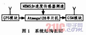
This design uses Atmega128 microcontroller as the central processor of the whole system, connected with MEMS acceleration sensor, GPs positioning module and GSM communication module.
Once the MEMS accelerometer detects an acceleration change, Atmega128 will analyze the data. If it is determined that a car accident has occurred, the GSM module will transmit the positioning information received by the GPS to the relevant department by texting or making a call. Quickly dispatched a rescue team to carry out rescue work; on the contrary, the system automatically resets and cycles detection. The system structure block diagram is shown in Figure 1.
This article refers to the address: http://
2 main hardware modules
2.1 MEMS Acceleration Sensor Module Accelerometer is an electronic device capable of measuring acceleration force. There are two types of angular accelerometers and linear accelerometers. The MEMS accelerometer model used in this system is ADX L202JE. This sensor etches a polysilicon surface micromechanical sensor in the same silicon wafer and integrates a set of precise information processing circuits, as shown in Figure 2.
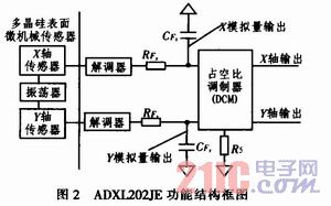
The sensor is mainly composed of a polysilicon mechanism using surface micromachining and a differential capacitor. Under the action of acceleration, the polysilicon structure will be offset to change the capacitance value. In the signal processing circuit, the change signal of the differential capacitor is demodulated by the modulator and sent to the duty cycle modulator through an RC filter (consisting of internal RFx and external CFx, RFx), and converted into duty by the modulator. A square wave proportional to the acceleration, the period of the square wave (T2) can be determined by Rs. This square wave can be directly sent to the microcontroller for processing, and the value of the acceleration is obtained by measuring the square wave period T2 and the pulse width T1 (Fig. 3) using a counter.
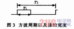
Acceleration: a=(T1/T2-Uog)/Ulg
Where: T2 is determined by the external resistor Rs, the relationship is T2=Rs/125MΩ; Uog is the duty ratio corresponding to 0g, the deformation value is 50%; Ulg is the duty cycle change value caused by the change of lg acceleration, For the ADXL202JE, a typical value for lg is 12.5%.
2.2 GPS Positioning System GPS (Global Positioning System) is the most widely used satellite navigation and positioning system, which is easy to use and low in cost. The main features of GPS are: global, all-weather, continuous and real-time navigation, positioning and timing functions.
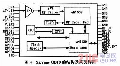
This module uses SKYnav GB10, the structure and its pins are shown in Figure 4. The module has low power consumption, anti-interference ability and strong anti-blocking capability. It has 12 data parallel receiving channels, including 8 data bits, 1 start bit, 1 stop bit, no correction bit, and output power. The level is CMOS and the current is 1mA. The communication method is asynchronous serial communication. The circuit connection method is very simple. Just connect the TXD0 and RXD0 pins of this module to the RXD0 and TXD0 pins of the MCU respectively, and the data transmission can be performed. The default communication rate is 4 800. b/s, the acceptance frequency is 1 575.42 ± 1.0 MHz.
2.3 GSM communication module TC35 is a new generation wireless communication GSM module launched by Siemens, which can realize data, voice transmission, short message service and fax in the system scheme quickly, safely and reliably. The module operates from 3.3 to 5.5 V and can operate in both 900 MHz and 1 800 MHz bands, with power consumption of 2 W (900 M) and 1 W (1 800 M), respectively. In addition, the module also has a phone book function, multi-party call, roaming detection function, commonly used work mode has power-saving mode, IDLE, TALK and other modes. Bidirectional transmission of power connections, commands, data, voice signals, and control signals through a unique 40-pin ZIF connector.
The TC35i has 40 pins, and the 1 to 14 pins are power supply parts. Among them, the 1 to 5 pins are the power supply voltage input terminal VBATT+, the 6 to 10 pins are the power supply ground GND, and the 11 to 12 pins are the power supply terminals. The pin is the external output voltage (for external circuit use), the 24~29 pin is the SIM card connection end, and the 33~40 pin is the voice interface for receiving the phone handle. The 15, 30, 31, and 32 pins are control sections, and the 15 pins are the enable line IGT (Ignition). When the TC35 is powered up, the IGT must be given a low level greater than 100 mV for the module to start. The 30 pin is RTC BACK UP; the 31 pin is power down control: 32 pins are SYNC, and 16 to 23 pins are data input/output terminals.
Here, the SYNC pin is highlighted because it is a good reflection of the TC35's operating state. The SYNC pin can be used to output a synchronization sign-al or to control the output state of an LED when it is applied. The SYNC terminal controls the LED through a triode or gate. The SYNC terminal is connected to the base of the NPN transistor (such as 9013) through a resistor. The emitter is directly grounded, and the collector is connected to the negative terminal of the LED through a current limiting resistor. The positive terminal of the LED is connected to VCC. The working mode of the LED is completely similar to the synchronous signal, showing the working state of the TC35i: the LED light is off, indicating that the TC35i power is off, in the sleep, alarm or pure charging mode; 600ms light / 600ms off, indicating that the SIM card is not inserted, or Personal identity is not registered / has been logged out, or the network is searching, or administrator identification is in progress, or network registration is in progress; 75 ms on / 3 s off, indicating that the network registration is successful (control channel and management personnel exchange information completed) ), no incoming call; LED light is on, depending on the type of call, there are voice calls, data calls, in the state of establishment or completion.
The TC35 module sends SMS common text and PDU (Protocol Data Unit) mode. Using Text mode to send and receive SMS code is simple and easy to implement, but the biggest disadvantage is that it can't send and receive Chinese text messages. The PDU mode not only supports Chinese text messages, but also can send English text messages.
Here is the text sending text case:
1) Set the short message center at+csca=“+813800731500†(SMS center);
2) Set the SMS sending format at+cmgf=1(1-Text;0-PDU);
3) Send a short message (the content of the message is "Test")
At+cmgs=“number of destinationsâ€
>Test^z;
4) Get the message content (Once more), assuming Index=8
At+cmgr=8
The return information is as follows:
+CMGR: "RECREAD", "+8613225 168879", "10/03/15, 22:45:25+32"
Ni hao!
OK
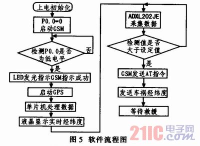
3 System software design The central processor and each module transmit information data through UART, the transmission baud rate is 9 600 b/s, the data format bit is 8 data bits, 1 stop bit, no parity. The software is written in C language, C language is easy to read, easy to transplant and manage. The software flow chart is shown in Figure 5.
4. Conclusion This paper designed a car accident automatic positioning alarm system. Real-time determination of acceleration, real-time display of latitude and longitude, and automatic transmission of information are realized. With the help of GPS global positioning system and GSM communication technology to provide a complete data communication platform, the goal of automatic positioning alarm is achieved, which greatly reduces the death caused by untimely rescue.
LED Ceiling Light, LED Down Light, LED Recessed Ceiling Light
LED Ceiling Light
LED Ceiling Light, LED Down Light, LED Recessed Ceiling Light
Shenzhen Ri Yue Guang Hua Technology Co., Ltd. , https://www.ledlightinside.com