Capacitive sensors are commonly used in general-purpose mobile devices. This article will use COMSOL MulTIphysics's AC/DC module to briefly explain the capacitive sensor. A simplified schematic of the core components of a capacitive touchscreen sensor will be presented, how to visualize the color of the logarithm of the electric field value.
Touch screen technology is used in consumer electronics such as cell phones, e-book readers, computers, and even watches. Some form of capacitive sensing is used in a large number of touch screens. Let's take a look at how to analyze such capacitive sensors using the AC/DC module of COMSOL MulTIphysics.
Introduction to capacitive sensingFor capacitive sensors such as those used in touch screen devices, there are a large number of conductive electrodes embedded in a transparent dielectric material such as glass or even a sapphire screen. These electrodes are themselves very thin, made of an almost completely transparent material and are invisible to the naked eye.
Let's start with a very basic structure that includes two electrode arrays placed at 90° angles, as shown in the following image.
Please note that the actual touch screen is more complicated than what we see here, but the simulation techniques are basically the same.
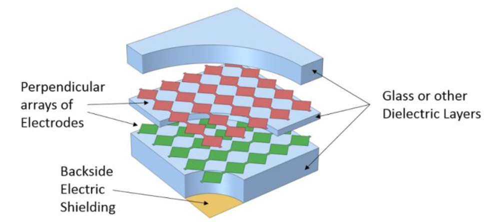
Simplified schematic diagram of the core components in a capacitive touch screen sensor (not proportional)
When a voltage difference is applied between any two or more electrodes, an electrostatic field is generated. Although the electrostatic field is strongest between the electrodes and the area surrounding the electrodes, it extends outward a certain distance. When a conductive object (such as a finger) approaches this area, the electric field will change, enabling detection of changes in the combined capacitance between the two active electrodes. It is through this capacitance difference that we sense the position of the finger that is touching the screen.
When a potential difference is applied between the partial electrodes, the other electrodes may be individually electrically insulated or electrically connected as a whole, but still in an electrically insulated state. Therefore, they can have a constant but unknown potential.
The ability to properly simulate these electrodes, surrounding metal shells, and other dielectric objects is the key to calculating capacitance changes. Let's take a look at how to use the features of the AC/DC module to achieve this.
Capacitive sensor in an analog watchFor such a relatively small device, we can simulate the entire structure; the sensor is only 20 * 30 mm in size and the distance between the two electrodes is 1 mm. For larger touch screens, it is more sensible to consider only a small area of ​​the entire screen.
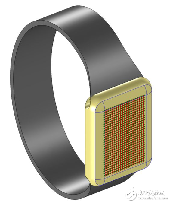
A capacitive sensor embedded in a glass dial (transparent). The strap and case are for visualization purposes only.
As shown in the figure below, the analog domain is a cylindrical area. This area contains the glass screen, the fingers, and the air around the watch. We have reason to believe that the effect of ambient air size will decrease rapidly as the size increases.
Boundary conditions usedHere, the boundary of the air domain is set to a zero charge condition to simulate the boundary as free space. In addition, two of the parallel electrodes are set to the ground boundary condition, and the voltage field is fixed to zero. Two of the vertical electrodes are set to terminal boundary conditions and the voltage is a constant value. The terminal boundary condition will automatically calculate the capacitance. All other boundaries are simulated by the floating potential boundary conditions.
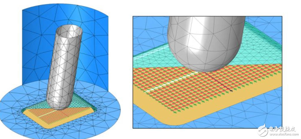
Visualize the finite element model. Fingers (gray), electrical shielding (orange), and all unexcited electrodes (red and green) were simulated by floating potential boundary conditions. A potential difference is applied to the two electrodes (white and black). Part of the dial (cyan) is hidden. Electrically insulated boundary conditions (blue) are used for all other faces. The air and dial are meshed. For the sake of clarity, only the mesh on a partial surface is shown.
The floating potential boundary condition is used to represent a set of surfaces whose charge is freely redistributable. The purpose of the setting is to simulate the boundary of an object with a constant but unknown potential. This is the result of applying an electrostatic field externally.
This type of floating potential boundary condition is used on several sets of surfaces, such as the underside of a watch, which represents the electrical shielding under the glass envelope. The currently unexcited electrodes are part of a separate floating potential boundary condition (assuming all electrodes are electrically connected together). Note that the floating potential group option can be used to allow each physically independent boundary to float to a different constant voltage. It is also possible to electrically connect any combination of electrodes by grouping them into the same group.
The floating potential boundary condition is also used when the finger boundary (included in the model). It is assumed that the human body is a good conductor relative to the air and dielectric layers.
Material usedOnly two different materials are used here. Preset air material is used in most domains and the dielectric constant is set to 1. The screen uses a preset quartz glass material to give it a higher dielectric constant.
Although the screen itself is a sandwich-like sandwich of different materials, we can assume that all layers have the same material properties. Therefore, it is not necessary to explicitly simulate each boundary between them; all layers are treated as a single domain.
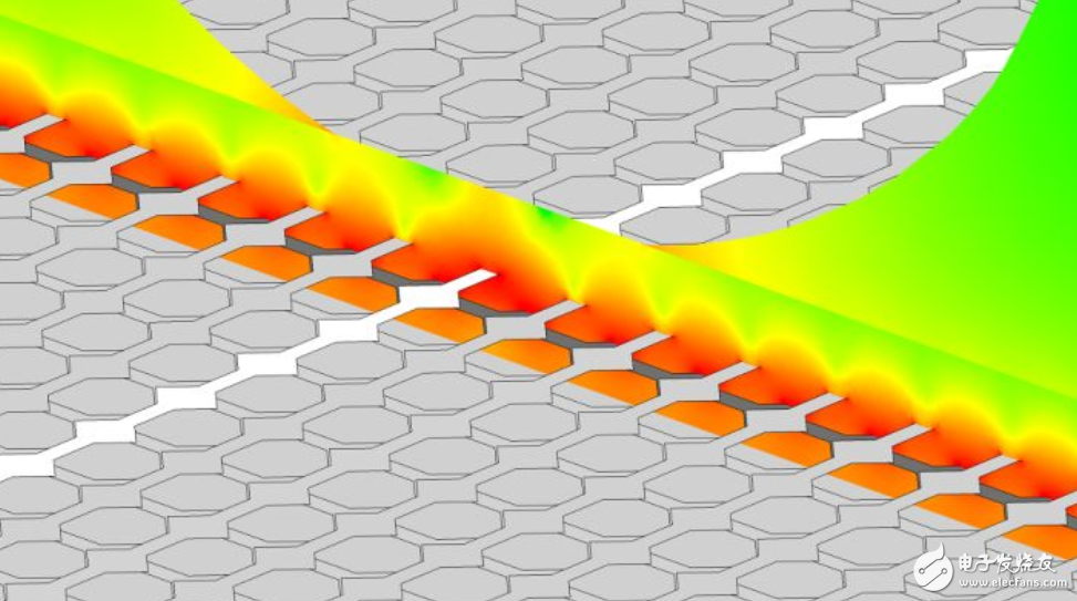
Visualize the color of the logarithm of the electric field value. Since the finger is regarded as a floating potential, its internal electric field is negligible.
Accuracy obtained with adaptive mesh refinement
To get accurate results, a finite element mesh with sufficient refinement is needed to resolve the spatial variation of the voltage field. Although we don't know where the most dramatic changes in the voltage field will appear before we calculate, we can use adaptive mesh refinement to let the software decide for itself where smaller grid cells are needed.
We used several adaptive mesh refinements and the results are shown in the following table. These results were obtained on a computer configured with a 3.7 GHz eight-core Xeon processor and 64 GB of memory:
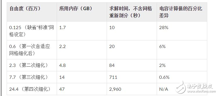
As can be inferred from the above table, we can start with a very coarse mesh and then use adaptive mesh refinement to get a more accurate capacitance value. However, doing so will increase memory usage and increase solution time. The percentage difference in capacitance is for the most detailed case of the mesh.
Calculating the capacitance matrixSo far, we have only focused on the calculation of the capacitance between the two electrodes in the array. In fact, we want to be able to calculate the capacitance between all the electrodes in the capacitor array, the capacitance matrix. This symmetrical square matrix defines the relationship between the applied voltage and charge on all electrodes in the system. For a system consisting of n electrodes and a ground, the matrix is:
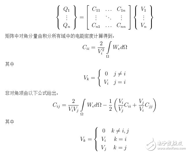
These diagonal and off-diagonal items are automatically calculated by the software and will be covered in more detail in subsequent blog posts.
summaryWe have studied an example of using a static analog function of an AC/DC module to solve a capacitive touch screen device. Although the geometry has been simplified for the purposes of this introduction, the techniques presented are also applicable to more complex structures.
When solving such a finite element model, it is very important to study the convergence of the obtained physical quantities (in this case, usually the case where the capacitance is refined relative to the mesh). The adaptive mesh refinement feature greatly increases the automation of the model validation step.
Shenzhen Scodeno Technology Co.,Ltd , https://www.scodenonet.com