Engineers of common oscilloscopes will find a phenomenon. When the oscilloscope stops sampling, the original waveform will be vertically enlarged and there will be jagged. What is the reason? Here is a quick analysis with everyone.
First, the step waveformIn this paper, the ZDS4054Plus oscilloscope is used as the test tool. As shown in Figure 1, the waveform is sampled in the 200mv/div position, and the waveform is relatively stable. After stopping sampling, if the vertical gear is adjusted to 50mv/div, the waveform will appear severely jagged, as shown in Figure 2. Many people are puzzled for this. Why is this happening?
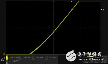
Figure 1 original signal waveform
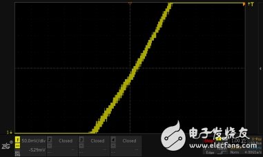
Figure 2 enlarged waveform
Second, the reasons explain1, in the running state
When the oscilloscope is in [Run], the oscilloscope analog front end will always adjust the amplitude of the signal to the appropriate range of the ADC according to different vertical gear positions, and then quantize, so the waveform in the running state is enlarged, there is no sawtooth phenomenon. .
· In the 200mv/div position, the vertical resolution (25 LSB/div) is 8mv
· In the 50mv/div position, the vertical resolution (25 LSB/div) is 2mv
The smaller the vertical scale, the higher the resolution, the higher the accuracy of the acquired waveform measurement. This is why the recommended waveform is as full as possible.
2, in the stop state
In the stop state, the waveform is not acquired, that is, the stop state, regardless of the vertical gear change, will still maintain the vertical accuracy of 8mv at stop (200mv/div), so when the vertical direction of the waveform is enlarged by 4 times (50mv/div) ), then the vertical distance between the sampling point and the sampling point will become larger, of course, this is only digital amplification, the oscilloscope will perform interpolation and hold at this time, the interpolation will keep the waveform connected in the form of a step, which is also jagged. the reason.

Figure 3 interpolation retention
Third, understand the misunderstanding: Interpolation is related to the interpolation algorithm?Earlier we mentioned the interpolation hold, then some engineers may think that it will be due to the interpolation algorithm caused by the sawtooth after the waveform is enlarged. After all, linear interpolation is connected in a point manner, and it is normal to appear jagged. The answer is no, the following is an analysis from the principle layer.
First explain what is the interpolation algorithm. For many oscilloscopes, there are different interpolation modes. The common ones are sinusoidal interpolation and linear interpolation. In actual use, if the sampling rate of the oscilloscope ADC is not enough to restore the real signal, we need to choose different Interpolation method for test analysis:
1, sinusoidal interpolation
Sine interpolation is the default interpolation method for the oscilloscope and the most common interpolation method. By sinusoidal interpolation, the true waveform signal can be restored accurately and smoothly. The use of curves to connect samples is more versatile. This method bends the signal waveform to produce a more realistic waveform than a pure square wave and pulse. Figure 4 shows the sampled sinusoidal interpolation and the observed amplified waveform.
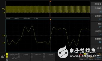
Figure 4 sine interpolation
2, linear interpolation
Linear interpolation is the simplest interpolation method with the least amount of calculation. A calculated value is inserted between adjacent sampled data points of the ADC according to a linear polynomial calculation. The inserted point is the value of the line connecting two adjacent sampling points. The waveform shown in Figure 5 is linearly interpolated to test the waveform. It is a waveform formed by a direct connection between points. The shape can be seen similar to the shape of the sawtooth wave. This interpolation method is limited to the signal of the straight edge. .
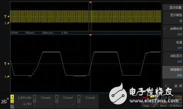
Figure 5 Linear interpolation
By comparing these two interpolation methods, you will find that the sine interpolation uses the curve to connect the sampling points, and the linear interpolation forms the waveform through the connection between the points. You may prefer the linear interpolation to form the sawtooth after the amplification. . It should be noted that the interpolation algorithm is performed during ADC sampling. When the sampling stops, the oscilloscope will perform interpolation and hold. The interpolation will keep the sampling points connected in a stepped manner. Therefore, the amplification under the oscilloscope stop is pure. Digital amplification is the result of oscilloscope interpolation, which is completely independent of which interpolation algorithm is used.
Fourth, summaryTherefore, no matter what interpolation method is used in the front, the amplified waveform will be displayed in a zigzag manner after the sampling is stopped. This is the reason for the interpolation and is completely normal. Therefore, when observing the waveform, we must make the waveform cover the entire screen as much as possible. If the waveform is jagged, it is also clear why the sawtooth comes from.
Stage Display,Rgb Laser Animated Light Show,Lighting Wall Lamp For Outdoor Building,Residential Holiday Lights
Kindwin Technology (H.K.) Limited , https://www.ktlleds.com