The transformation of the smart grid has initially achieved the precise positioning of the grid line faults. At least let the lineman who looked for the fault point in the past with the flashlight in the mountains and rivers is a lot easier to see how to achieve.
The power outages we have experienced are not too long. Any power grid failure in the city will be promptly remedied by the repairman. However, if the electricity that is transported across the Dashan River to the county or town is stopped, the lineman will have to Following the investigation of the Dahe Mountain, the ancient beacon tower has been replaced by the radio of the Mianbian post. The wireless fault indicator also builds a new beacon in the smart grid.
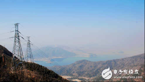
Figure 1 Electric tower between the mountains and rivers
China's suburbs and rural areas are vast and scattered, and the central city's power transmission line is long and the environment is harsh. The risk of manual maintenance is high, low efficiency and high cost. According to the national grid planning in the past three years (2017-2015) In the year, 120 billion RMB was invested in power grid transformation, mainly for D and E users (suburban and rural), of which 20 billion were invested in distribution automation transformation, and this trend will continue and deepen in the next three years.
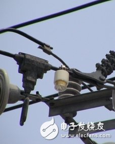
Figure 2 Fault indicator for overhead cables
Therefore, real-time monitoring of the operation status of large-area power grids, accurate understanding of fault nodes and fault types, and formation of a closed-loop automatic repair indication system, has a direct impact on the intelligence level of the smart grid, which contains a huge market.
Grid fault indication system structureThe grid fault indication system has three layers, which are fault acquisition layer, data transmission layer, background monitoring layer, fault collection sensor and display. The sensor is responsible for detecting the current passing through the cable. The display is responsible for judging the current information transmitted by the sensor. The fault indication action is made, and the judgment result is directly transmitted to the background monitoring layer through the data transmission layer, and the maintenance node is directly sent to the faulty node for repair. The block diagram of the grid fault indication system is shown in Figure 3.
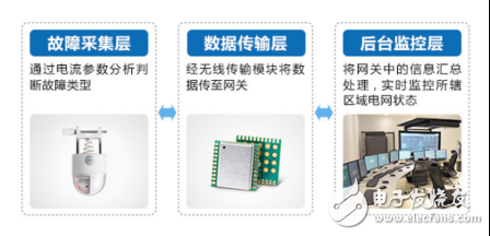
Figure 3 grid fault indication system block diagram
Due to the harsh working environment, the fault indicator needs to have the following three characteristics:
1, low power consumption for a long time online operation
Using protective coating and shell material, it can adapt to various environmental uses, such as immersion in water, high salt spray and extreme heat and cold, and can be installed in outdoor or cable branch box for a long time, requiring low power consumption of equipment;
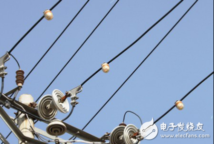
Figure 4 Fault indicator on overhead cable
2, far and near distance fault indication
The fault information can be transmitted to the gateway through wireless transmission to the maintenance personnel in the background. At the same time, high-brightness LEDs must be provided. When the faulty line is found at night, the fault alarm position can be accurately found within 300m.
3, the fault indication automatically reset
After a fault occurs, in the absence of current and voltage, it is automatically reset according to the set time, and can be automatically reset to the normal state at the next power transmission, and the abnormal information and the reset state are transmitted to the background through wireless communication.
Wireless data transmission layer solution: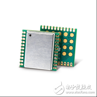
Figure 5 ZM470SX-L data transmission scheme
Advantages of ZM470SX-L for grid fault indication system1. Low power consumption
· Module integrates +12dBm adjustable power amplifier and can achieve more than -110dBm receiving sensitivity, link budget can meet most of the short-range communication needs, integrate industry-leading power control technology, reduce module power consumption Lowest, ideal for low power applications where high power requirements are required.
2. Industrial quality, anti-jamming
· Industrial quality can cope with harsh environments such as coastal high salinity and high temperature humidity to ensure stable transmission.
3. Multi-level adjustable transmit power
· The module integrates a power amplifier of up to 12.5dBm and provides -8.5~12.5@Step 3dB multiple adjustable power levels, which can freely adjust the signal coverage according to the position of the fault indicator.
Similar applicationsIn addition to being used at the branch of the overhead cable feeder, the grid fault indicator can also be directly installed in box-type transformers, various ring network cabinets, cable branch boxes, and substation in and out lines.
Media Converter,Fiber Optic Converter,Din Rail Media Converter,Poe Fiber Optic Media Converter
Shenzhen Scodeno Technology Co.,Ltd , https://www.scodenonet.com