This article introduces DCDC light-load working mode technical articles to share with you, especially the burst mode as the patent of Sprinter. For a long time, many companies that want to design light-load and high-efficiency power ICs have a headache. Nowadays, light load efficiency has become a basic requirement of many power ICs. Some products such as AOZ3015, 12V-5V/10mA light load efficiency has reached more than 85%.
At present, the application of high frequency and high efficiency DCDC converters is more and more extensive. Typically at full output load, the DCDC converter operates in CCM, continuous current mode. However, when the output load of the system is from full load to light load and then to no-load change, the operating mode of the system will also change accordingly.
The step-down Buck converter is taken as an example to illustrate the operating mode of the DCDC converter at light load. The buck Buck converter has three modes of operation at light load: burst mode, skip mode, and forced continuous mode. The working principle of these three modes and their advantages and disadvantages will be explained in detail below. In practical applications, the corresponding operating mode should be selected according to the specific requirements of the system for output ripple and efficiency.
1 skip pulse modeFor a constant-frequency conventional non-synchronous Buck controller, usually the current of the inductor operates in CCM continuous current mode, and the average current of the inductor is the output load current. When the load current decreases, the average current of the inductor will also decrease; when the load current decreases, the converter enters the critical current mode. At this time, if the load current is further reduced, the current of the inductor returns to 0, and the switching period has not ended. Due to the reverse blocking action of the diode, the current of the inductor is maintained at a value of 0 for a period of time, and then the switching period ends. The next turn-on period, when the converter is in a fully discontinuous current mode.
After the converter enters the discontinuous current mode, if the load current is still further reduced, in order to maintain the output voltage regulation, the turn-on time of the high-side switch tube will be reduced until the minimum on-time of the controller is reached. After the turn-on time of the high-end switch reaches the minimum on-time of the controller, if the load current is still reduced, the controller must be shielded to jump off some of the switching pulses to maintain the output voltage regulation. This control method is the skip pulse mode.
The synchronous Buck converter detects the current of the lower tube. When the current of the lower tube is close to zero, the system works in a non-synchronous manner, that is, the lower tube does not work, and the anti-parallel diode inside the lower tube is provided to provide a freewheeling circuit. .
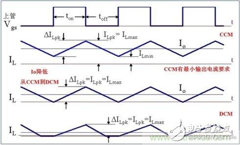
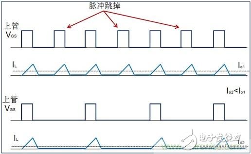
Figure 1: Jump pulse mode
The skip mode provides constant current discontinuous current operation over the widest input current range, preventing reverse inductor current. Since the controller allows the regulator to jump off some unwanted pulses, it improves the efficiency of light loads compared to continuous mode operation, but its light load is not as efficient as burst mode operation, and its light load output ripple is not as good as continuous mode. operating. The skip mode does provide a compromise between operating efficiency and noise.
2 burst modeThe schematic diagram of the Buck Burst Mode is shown in Figure 2. VFB is the output voltage feedback pin, VEA is the voltage error amplifier, VREF is the reference voltage, the upper limit voltage and the lower limit voltage of the burst operation mode comparator are VH and VL, and the change of the output load is detected by detecting the ITH pin voltage VC.
During normal operation, the system will not enter the burst mode. The burst mode comparator will not work. When the output load decreases, the output voltage will increase and VFB will increase accordingly. Since VEA is negative feedback, VC will decrease. . When the output load is reduced to a certain value, after the system enters the light load mode, the burst mode comparator starts to work, taking over the control of the ITH pin voltage VC, and the output signal of the burst mode comparator causes the control circuit to The output of the high-side MOSFET is turned off, and the high-side MOSFET stops switching. At this time, the input no longer transfers energy to the output, and the large output of the output will maintain a low output load, so the output voltage is slowly reduced, and VFB is correspondingly reduced. VC has increased.
As the output voltage continues to decrease, the voltage of VFB continues to decrease, and VC continues to increase. After a long period of time, the VC voltage will increase to equal VH, the burst output mode comparator output signal will be inverted, the control circuit will enable the high-side MOSFET drive output signal, the high-side MOSFET enters the switching operation, and the system enters the normal PWM operation due to The input energy is greater than the energy consumed by the output load, so the output voltage will increase.
When the output voltage is raised to a certain value, the VC voltage is lowered, and when the VC voltage is lowered to VL, the burst operation mode comparator output is flipped again, the drive signal of the high-side MOSFET is turned off again, and the system stops working again. Repeatedly, this mode of operation is the burst mode of operation.
The burst mode comparator controls the high-side switch tube operation. The high-side switch tube works for a short time, and the time for stopping the operation is very long, which greatly reduces the switching loss. During this period, many functions inside the chip stop working and reduce the internal The consumption of quiescent current increases the efficiency of the system.
On the other hand, because the high-side switch tube stops working for a long time, the output capacitor will maintain the energy of the output load, and the voltage of the output capacitor will decrease greatly. Therefore, the ripple voltage of the output capacitor is large, that is, the output ripple voltage is large. The upper and lower threshold voltages of the burst mode comparator determine the output voltage ripple value.
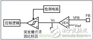
Figure 2: Burst Mode
This mode is somewhat similar to the hysteresis voltage mode, but the difference is that this mode determines the change in output load through internal detection to determine whether the system enters the light load burst mode. In the burst mode, when the comparator output signal flips the system into normal operation, the system works for normal fixed-frequency PWM, and the high-side MOSFET enters normal PWM operation. At this time, the system works in continuous PWM mode or intermittent and continuous PWM coexist. Mode, energy is quickly transmitted to the output, and stops working after a few cycles of operation.
3 forced continuous modeThe forced continuous mode is mainly for the synchronous Buck converter. In normal operation, the forced continuous mode and the skip pulse mode work in the CCM mode. When the output load is reduced and reduced to a certain value, as described above, the skip mode will enter the DCM mode by the CCM. When the current of the inductor is 0, the freewheeling diode will naturally turn off and maintain the off state until the next one is entered. Open in the cycle.
For forced continuous mode, the current in the inductor is 0. Since the synchronous switch is still on, the output capacitor voltage will be reversely applied to the inductor to reverse the inductance, and the inductor current will increase from 0 to a certain value. Value, then the synchronous tube is turned off, the main switch is turned on, the input voltage is applied to the inductor, the voltage across the inductor is a positive voltage, the current of the inductor will increase positively from a certain negative value, and continue to increase positively after 0 A certain value, this is also the so-called output current backflow phenomenon.
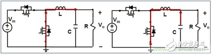
Figure 3: Forced continuous mode
The main switch and the synchronous switch are operating at each switching cycle, so the power consumption of the switch is large and the efficiency of the system is extremely low. Under low output load conditions, during each switching cycle, when the high-end main switch is turned on, the energy transferred from the input to the output load is greater than the energy required by the actual load, so the conduction of the synchronous switch must be relied on to make the output voltage The inductor is reversely excited to store excess energy in the inductor to maintain output regulation. This part of the energy is only exchanged back and forth in the inductor and is not consumed in the actual load. Since the inductance has magnetic loss (power loss in the core) and copper loss (loss of the wire resistance), the efficiency is further reduced. However, it is precisely because the main switch and the synchronous switch are operating at every switching cycle. Even under light load conditions, the energy of the input and output can be translated at each switching cycle, so the ripple of the output voltage Also the smallest.
This least efficient mode of operation is suitable for some specific applications. In this mode, the output can be used for both current and current sinking, so it can be applied to the supply of DDR memory. In addition, in some communication systems, low output voltage ripple is required even under light load conditions, so this mode of operation must be used, and efficiency is not a major consideration. The output ripple voltage and frequency are constant over the entire load variation range, which is easy to filter out noise, and is suitable for applications requiring low interference noise such as communication. In the forced continuous mode operation, the output current is reversed, and then the switch tube dead time, the current of the inductor charges the input capacitor, and the voltage is increased. The actual input voltage is checked to the maximum value of the relevant component. .
4 Comparison of the results of the three modesDesign a synchronous Buck converter with an input voltage of 3.3V and an output voltage of 2.5V. The output full load current is Io=1.25A, the light load current Io=50mA, the operating frequency is 1MHz, the inductance value is L=2.2uH, and the output capacitance is Choose a 22uF ceramic capacitor.
It can be seen from Fig. 4 that under the light load output current of 50 mA, the current of the inductor when the system operates in the skip mode is DCM mode, and the current of the inductor of each switching cycle passes through 0 and remains for a period of time before entering the next switching cycle; When operating in burst mode, the intermittent time of the main switch stop switch operation is 9uS, and then the switch operation is 3uS, the output voltage ripple peak-to-peak value is as high as 20mV; when the system works in forced continuous mode, the inductor current continues to reverse after 0 Increase to -100mA, then increase from -100mA forward, continue to increase positively to maximum after 0. The output ripple is small, and the looping of the inductor will affect the efficiency of the system.
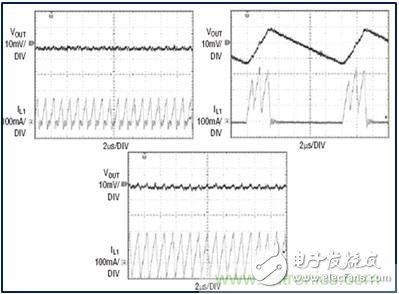
(a) skip mode (b) burst mode (c) forced continuous mode
Figure 4: Light-load three operating mode waveforms (Vin=3.3V, Vo=2.5V, Io=50mA)
From Figure 5, we can see the efficiency of the three modes at light load and the ripple of the output voltage. In the three modes, the burst mode has the highest light load efficiency and the maximum output voltage ripple, and the forced continuous mode has the lowest. Light load efficiency and minimum output voltage ripple, the skip mode is somewhere in between.
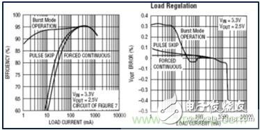
(a) Comparison of three modes of efficiency (b) Comparison of output ripple of three modes
Figure 5: Light load three mode efficiency and output ripple
References: LTC3411 Data Sheet
Screw Clip Terminal Blocks,Ground Screw Series Terminals,Din Rail Mount Terminals Block,Screw Ground Terminal Blocks
Wonke Electric CO.,Ltd. , https://www.wkdq-electric.com