Failure phenomenon:
When a Millennium Sea Lion car equipped with a 4Y engine is driving at 60-70km/h, the pointer of the speedometer often jumps.
Troubleshooting:
According to the information provided by the owner, the speedometer is normal when the speed is lower than 60km/h, and after 60km/h, the hand is raised and there is a jump. The test was carried out 10 times in a row, and this phenomenon occurred 3 times, and the amplitude of the 3 beats was different. First, the fault code is read by the Jinde K81 decoder, and the result is displayed without fault code.
The extraction of the sea lion 4Y engine speedometer signal is done by a Hall sensor. The sensor is inserted on the output shaft of the transmission, and the Hall element is driven by the helical gear to output a square wave signal. The speedometer receives this signal and converts it into a corresponding one. The magnetic field force pushes the pointer by one angle to show the speed value. From the nature of the fault, this is an irregular gap fault. For this fault phenomenon, it is necessary to pay attention to the timing when measuring. Only when the fault phenomenon occurs, the detected data is meaningful. The car's speed sensor has 3 wires, one wire is the 8V sensor power supply, one wire is the sensor ground wire, and the third wire is the 4.5V sensor signal wire. The speedometer controller calculates the speed of the vehicle through pulses on the signal line.
According to the analysis, this amount of jitter may be generated by a certain interference signal, and the strongest interference signal on the car is the ignition system. To confirm whether the ignition system generates interference or not, please only use the Jinde K80 oscilloscope to drive the "mirror mirror". Come here. If the ignition system interferes, the waveform should be as shown in Figure 1 when the fault occurs. However, the waveform when the fault is actually detected is shown in Figure 2. The waveform when the fault occurs is shown in Figure 3 and Figure 4.
Waveform analysis:
If the 5V signal line of the speedometer sensor is intermittently grounded, the signal waveform should be lowered from 5V and the abrupt portion will be at a right angle.
If the sensor power line, ground line, and signal line are intermittently disconnected, the sensor signal waveform should return to the 5V position, and the abrupt waveform should be at right angles or burrs.
If the accuracy of the triode in the sensor is not high or the performance is poor, there will be rounded corners in the signal waveform, which is caused by the characteristics of the triode, and the triode is operating in the saturation region.
The Hall-type vehicle speed sensor used in the vehicle has two rounded corners in the waveforms of Figure 3 and Figure 4 when the fault is detected. This shows that the additional rounded signal is generated by the triode of the Hall-type speed sensor. That is to say, the fault waveform is caused by poor performance of the vehicle speed sensor. 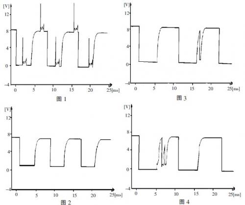
Troubleshoot after replacing the speed sensor.
Maintenance experience:
In practice, the most common method used by maintenance personnel for faulty vehicles is to first use the decoder to query the fault code, then repair according to the fault code, and finally clear the fault code. However, if the repair failure cannot be ruled out, some maintenance personnel feel that it is impossible to start with the next step. In fact, some fault codes of electronically controlled vehicles may be caused by poor performance of the components themselves, or may be broken or shorted by wires, or may be caused by other sensor failures or interference signals. Use the oscilloscope to diagnose these accidental or difficult faults. The effect is very good. The oscilloscope can display the relationship between the measured voltage and time in real time with the waveform, which is widely used in automotive diagnosis. Now the most important thing in car repair is diagnosis. You can understand car diagnosis in this way: “diagnosis†is to obtain useful data by “looking, smelling, asking, cutting, smelling†or using a variety of testing equipment or instruments. Accurately analyze the cause of the fault and find the premise and basis of the fault location. However, if the test instrument or equipment is not displayed correctly, as some domestic car decoders display false ignition waveforms and false data streams, the correct diagnosis result becomes no. The wood, the passive water. In addition, "broken" is the analysis and judgment. Based on the correct test data of the previous "diagnosis", the correct judgment is obtained through correct thinking.
This article refers to the address: http://
Shareconn development Co.,Ltd assemble high quality RF extension cables, such as BNC cables, SMA cables, MCX cables, Farkra cables, SMB cables and so on.
Accommodates a wide range of medium to miniature sized RG coaxial cables in a rugged . Medium size design.Provides customer flexibility in their design and manufacturing with a durable connector. Available in many styles: Plugs (Straight and Right Angle) and Jacks (Panel Mount , Bulkhead Mount ). Meets many customer application demands.
RF Extension Cable Assembly,RF Extension Coaxial Cable,RF Coaxial Cable,RF Aerial Cable Extension
Shareconn Development CO.,LTD , http://www.share-conn.com