1 Introduction
H.264 is based on the coding standards previously formulated by ITU-T, ISO / IEC and other organizations. It is the same as most of the current international video compression standards, such as H.264, H.263, MPEG-2 MPEG-4 is a hybrid coding technology that uses block-based discrete cosine transform and quantization. The block-based discrete cosine transform has high compression rate and low computational complexity. Easy to implement and other advantages. H.264 has the following features: 50% less bit rate than H.263 + and MPEG-4 (SP); strong adaptability to channel delay; improved error recovery capability; complexity can be designed in stages to adapt to different Application of complexity; introduce advanced technology, including 4 × 4 integer transform, intra-frame intra-space prediction, 1/4 pixel precision motion estimation new technology brings higher coding ratio, while greatly increasing the complexity of the algorithm. Therefore, H.264 technology has been widely used in high-definition video codec equipment.
Video decoding algorithms such as entropy decoding, inverse quantization, inverse transform, intra prediction, inter-frame luminance interpolation, inter-frame chroma interpolation, and de-blocking filtering are called core modules, reducing the waiting time of these core modules to speed up the work of the decoder Of great significance. In this paper, on the DSP-BF533 platform, using the idea of ​​software pipelining, a new type of optimized design scheme is proposed for collaborative work between software modules.
2 H.264 decoder principle
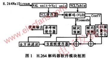
The H.264 encoder structure system consists of the following parts: network data extraction layer (NAL), VAL buffer, entropy decoding, inverse scan and inverse quantization and inverse transform, inter prediction, intra prediction, image reference frame buffer, and Block filtering, as shown in Figure 1. First, the NAL unit data is obtained from the code stream, and the sequence parameter set, image parameter set, and image data are parsed through RBSP. Store the data and parameters in the VCL buffer, and then entropy decode in the video coding layer (VCL Table). The entropy decoding module (VLD) parses all parameters and reference image indexes, etc., and provides various control information and residual data. Through inverse quantization and inverse change, first convert one-dimensional data into a two-dimensional array or matrix, and then map the sequence of transform coefficient quantization values ​​to corresponding coordinates through the inverse scanning process. There are two modes: inverse zig_zag scanning and inverse field scanning. Then read the data to read and make judgments, intra prediction and inter prediction, then integrate all the data of prediction and inverse transform and inverse quantization, and finally perform block filtering, which can greatly reduce the blockiness caused by prediction and quantization, thus Get better subjective image quality and objective performance. At the same time, the restored image can also be selected as the reference frame for the subsequent processed image.
3 DSP-BF533 decoder design and optimization
3.1 Decoder software design block diagram
According to the characteristics of DSP-BF533's embedded memory controller (DMA), design a decoding process that integrates DMA, as shown in Figure 2. Add two steps related to DMA to the ordinary decoder. Step 1 is to read data from off-chip memory; step 2 is to output the processed data to off-chip memory.

The specific process can be seen from Figure 2: ①The top data is divided for the next macroblock, and the data before the residual data is divided. At the same time provide intra prediction, reference image index and vector for decoding; ② start DMA to read the segmented data, which also needs to read the decoded reference image index and vector; ③ perform intra prediction on the image data; ④ use the bottom segment to read Inverse transform and inverse quantization of the input mapping data; ⑤ Reconstruct the image by filtering; ⑥ Output the image data to the off-chip and on-chip memory through DMA; ⑦ Perform bottom data division on the next macroblock, and then take out the mapping data for download A macroblock decoding uses mocking.
In order to avoid the DSP core waiting for the DMA to read the human data, the decoded data is divided into the top data and the bottom data from the macroblock in advance, the top data includes the data before the residual data, and the remaining data is the bottom data. If the data has been divided in advance when a P frame arrives, then DMA starts. When the DSP core is decoding the current macroblock, the DMA reads in the next macroblock. If the reference data of the current macroblock needs to be used, this data can also be input to the on-chip memory through DMA after decoding. Because the data at the top of the current macroblock has no reference value for the filtering of the next macroblock, the data at the top of these macroblocks is DMA transferred to the external memory. The first macroblock of this design does not enter the decoding process, because a series of reference images and parameters are not set in the initial state, so the first macroblock is only to set the decoder reference image and parameter line initialization, as the next macroblock Use for decoding. Macro block data division and DMA data reading can be performed in parallel during decoding, that is, the parameters of the next macro block can be set and the decoded data can be read when the current macro block is executed, which can reduce the waiting time between each module ,Improve work efficiency. The process that can be executed in parallel is shown as an elliptical box in FIG. 2.
3.2 New algorithm of software pipeline
In many designs, processes such as decoding parameter preparation, decoding, and DMA data output are executed serially in order. The design arranges these three processes for parallel execution, making full use of the parallel execution of DSP-BF533 instructions to reduce software modules. The waiting time between.
The following uses a 4 × 4 macroblock matrix as an example. First, the 4 × 4 matrix is ​​marked with the coordinates of 4 rows and 4 columns, and then the program processing is divided into 5 stages. Their states correspond to 1, 2, 4, 8, 16, for state machine calculation, as listed in Table 1. CAVLC is a process of parsing the read data and providing data such as parameters and reference images for subsequent image integration and reconstruction. Hl_decode is an advanced decoding process, that is, a process of comprehensively reconstructing images according to prepared conditions. DMA is the transfer process of decoded data. Analysis according to Table 1 and Table 2: When a new frame of image arrives, the current state label is 1, and only CAVLC is executed at this time; when the coordinate is x = 1, y = 0, enter the second state, the current State label is 2, CAVLC and hl_decode are executed in parallel; when running to coordinate x = 1, y = 1, enter the third state, label is 4, 3 modules are executed in parallel at the same time; when coordinate y> 4, enter the first The four states are labeled 8, and only hl_decode and DMA are executed in parallel. CAVLC has completed preparations for decoding all macroblocks; then judge x> 0 and enter the fifth state. The label is 16, and only the DMA module is running at this time.

Therefore, when the first macroblock is decoded, it is in state 1, then 4 consecutive macroblocks are in state 2, then 11 consecutive macroblocks enter state 3, then 1 macroblock is in state 4, and the last 3 macroblocks enter the state 5.
If it is assumed that the execution time of CAVLC A, the execution time of hl_decode B, the execution time of DMA C, the total execution time of common algorithms T = 16A + 16B + 16C; the method time proposed in this paper T2 = A + 16B + 3C, therefore, obviously Reduced program execution time.
4 Test results
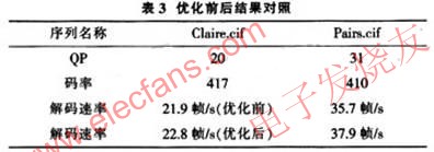
Test Claire.cif and Pairs.cif on the DSP-BF533 test platform. From the results of the test analysis: the optimized results improve the decoding rate and meet the real-time application requirements. The results are listed in Table 3.
5 Conclusion
For mobile video terminal applications, according to the characteristics of DSP, a new software pipeline algorithm is proposed to make the cooperation between modules closer, make better use of the free time of program operation, reduce program waiting time, and increase the decoding rate. Experimental testing The program has reached the real-time decoding requirements for CIF images, and is further optimized in the future to achieve higher and more reliable decoding efficiency, making the design based on DSP-BF533 fully scalable from wireless 3G network, digital TV, to IP network , Media storage formats and other different fields.
Military Battery Pack has a strick requirements in working efficiency ,circuit protection ,cycle test ,working temperature and anti-impact.it refers to the Battery Pack which follows a strict standardard well known as international military standard or USA military stand ,in the other size ,the Military Battery pack is divided to Non-Rechargeable Military Battery Pack and rechargeable military battery pack.
Non-Rechargeable Battery:
BA-3030/U(LR20/FR20): 1.5V alkaline battery (and lithium iron disulfide);
BA-3042/U(LR14/FR14): 1.5V alkaline battery (and lithium iron disulfide);
BA-3058/U(LR6/FR6): 1.5V alkaline battery (and lithium iron disulfide);
BA-200/U: 6V primary zinc chloride battery;
BA-3200/U: 6V alkaline battery;
BA-5372/U: 6V/500mAh lithium manganese dioxide battery;
BA-5800/U: 6V/7.5Ah lithium sulfur dioxide battery;
BA-5390/U: 15V/30V,10Ah/20Ah lithium manganese dioxide battery;
BA-5590/U: 14V/28V,6.4Ah/12.8Ah lithium sulfur dioxide battery;
BA-3590/U: 15V/30V,7Ah/14Ah alkaline battery;
BA-3791/U: 15V,16Ah alkaline battery;
BA-3386/U: 15V,15Ah alkaline battery
Rechargeable battery:
BB-590/U: 12V/24V,2.4Ah/4.8Ah Ni-Cd battery;
BB-390/U: 12V/24V,4.5Ah/9Ah Ni-MMH battery;
BB-390B/U: 12V/24V,4.5Ah/9Ah Ni-MMH battery, with [LCD" display ;
BB-2590/U: 14.4V/28.8V,7.5Ah/15Ah, lithium ion battery, with [LCD" display;
TLI-9380E: 14.4V/15Ah, lithium ion battery;
BB-2590/U: 14.4V/28.8V,7.5Ah/15Ah, lithium ion battery, with [LCD" display and SMBUS ;
BB-2791: 14.4V/15Ah, lithium ion battery, with [LCD" display and SMBUS ;
TLI-718: 14.4V/5Ah, lithium ion battery.

Military Battery Pack
Military Battery Pack,Rechargeable Battery,Deep Cycle Battery,Rechargeable Military Battery Pack
YFJ TECHNOLOGY (HK) CO.,LIMITED , http://www.yfjpower.com