1 Introduction
The development of fieldbus technology makes the control system a big step in the process from closed to open. The open control system based on the field bus began to enter the closed DCS system, becoming the development direction of process control. The FF (Foundation Fieldbus) fieldbus is an all-digital, serial, and bidirectional communication network. It is also a fieldbus designed specifically for applications in the field of process automation.
Based on the FF fieldbus-based network measurement and control experimental platform designed by the Shenyang Institute of Automation, the Chinese Academy of Sciences, this paper designs the liquid level feedback control loop of the dual-capacity water tank, and puts forward the application of the PID control algorithm to the FF site in conjunction with the specific controlled object. The feasibility scheme of the bus system has realized the PID control algorithm based on OPC technology on the basis of the OPC server MicroCyber.FFServer.1. Experiments show that the control effect of this scheme has better played the technical advantages of fieldbus and PID control, and achieved the expected control effect.
2. Network platform based on FF fieldbus
This system includes two parts: FF field bus part and field control model part, as shown in Figure 1. FF fieldbus includes low-speed fieldbus H1 and high-speed fieldbus HSE. The low-speed fieldbus H1 has a rate of 31.25 kbps and can be used for temperature, liquid level, and flow control applications. The signal type is voltage signal; the high-speed fieldbus HSE has a rate of 100 Mbps, and is generally used for advanced control, remote input / output, and high-speed factories. Automation and other occasions. The field control model can use the original equipment of the laboratory, thereby saving investment. The original analog instrument can be transferred to the field bus through the current signal to the field bus signal transmitter.
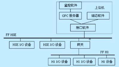
Figure 1 System software operation relationship
Taking the single-loop liquid level control as an example, the software operation in the host computer:
(1) HSE Init interface software, select the H1 network segment, the HSE interface program can interact with the HSE device in the Ethernet segment, and the H1 network segment device under the LD device to provide data access interfaces to upper-layer software such as configuration;
(2) Run the configuration program FF-Configurator configuration software, refresh the network segment to obtain the on-site device list and function block list of the system, and after refreshing the network segment, establish the application to complete the function block configuration, and the connection between the function blocks means that Signal connection for bus communication, as shown in Figure 2;
(3) The FF H1 and FF HSE OPC servers are refreshed every second to realize real-time data and historical data sharing and alarm functions of the device;
(4) Design SiaView monitoring software, create a new project, select PID in the object and drag it to the view. After connecting with OPC, you can get a PID function block operation panel after editing.
Select the IF-AI1 function block, IF-PID function block and FI-AO1 function block from the device in the engineering window of the configuration software and drag them to the application view to connect and configure a PID control loop, as shown in Figure 2. Connect the function blocks and establish the connection between the function blocks, so that the parameter values ​​can be transferred between the function blocks and the configuration information needs to be downloaded to the field device. To make the liquid level control loop operate correctly, you need to modify the parameter value of the function block, double-click the IF-PID function block, open the parameter window of the block, modify the TARGET parameter under the MODE_BLK item in the IF-PID to AUTO mode, and read the function block parameter In order to realize the automatic normal operation of the liquid level control of the single circuit. If you want to implement the scheme of applying advanced control algorithms to the FF fieldbus system, you only need to modify the TARGET parameter under the MODE_BLK item in the IF-PID to MAN mode, the specific settings are shown in Figure 3, and then realize the process variables through OPC technology Communication with control variables.
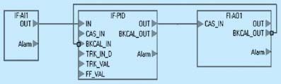
Figure 2 PID configuration strategy configured in the application window
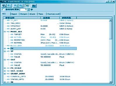
Figure 3 IF-PID function block parameter table when implementing advanced control algorithm
3. PID control scheme based on OPC
To realize the advanced control algorithm based on FF field bus, it is first necessary to implement conventional PID control as the basis. The software containing advanced control algorithm reads and writes information of hardware devices through the OPC interface (as an OPC client), and accesses process data through the OPC server. Overcome the differences between heterogeneous network structures and network protocols.
3.1 OPC server
The OPC server MicroCyber.FFServer.1 provided by Shenyang Institute of Automation, Chinese Academy of Sciences is used. The address space of the server is composed of all data items that can be read and written by the server. You can get the full name of the data items to perform related operations as needed. Figure 4 is a diagram of the address space of the OPC server. Use OPC technology to realize the communication between the client program written in VB6.0 and the OPC server, the real-time value of the liquid level in the server IF-PID-PV.VALUE, and custom variables such as the liquid level set value IF-PID-SP. VALUE, and then conduct algorithm control to get the control amount, and write the control amount into the item FI-PID-OUT.VALUE of the OPC server to control the controlled system.
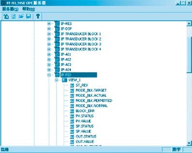
Figure 4 Address space diagram of the OPC server
3.2 OPC automation interface standard
(1) Automation interface
The OPC Foundation provides two types of interfaces for data access specifications to facilitate user software development in various environments: automation interfaces and custom interfaces. Based on the development of custom interfaces, deeper COM / DCOM knowledge is required, which is more obscure and difficult to understand, and the use of automated interfaces has the following advantages: client programs can easily apply interfaces without having to understand the detailed internal mechanism of the interface; Use event trigger mechanism; can generate a common dynamic link library (DLL) or control for all client applications.
(2) Communication mechanism of automation interface
The OPC client program accesses the OPC server through the packaged OPC automation interface dynamic link library, as shown in Figure 5. The dynamic link library translates the customized interface of the OPC server into the automation interface desired by the OPC client program for the client program to call. The OPC client program and the dynamic link library are in-process communication, and the communication between the dynamic link library and the OPC server is based on COM / DCOM, which can be either an in-process or local connection, or a remote connection. The packaged dynamic link library solves the interpretation of the custom interface and the communication between the two, thereby greatly simplifying the development of OPC client programs.
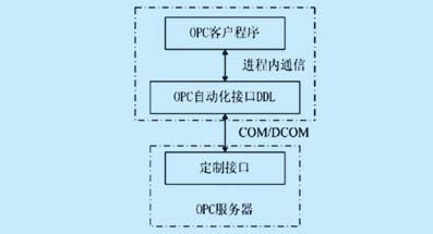
Figure 5 Communication between OPC client program and server
Yuhai Company is engaged to research and development of piezoelectric products and related piezoelectric products, the related piezoelectric products includes the piezo sensors and transducer.
The Ultrasonic Transducer is a kind of transducer that converts the ultrasonic signal into electric signal, or vice versa. Ultrasound transmitter and receiver is a transducer that can transmit and receive ultrasound. Ultrasound sensor is a kind of sensor, in essence, it is also a transmitter and receiver. The working principle of this kind of equipment is similar to that of radar and sonar. Active ultrasonic sensors can emit and receive reflected waves, and determine the distance of the target by measuring the time interval between transmission and reception. Passive Ultrasonic Sensor is actually a microphone that can convert ultrasonic signal into electrical signal.
According to the working principle and materials used, the ultrasonic transducer has Piezoelectric Transducer, electrostatic transducer (capacitive transducer), magnetostrictive transducer, electromagnetic acoustic transducer, mechanical transducer and other types [1].
Ultrasonic Sensor
Ultrasonic Sensor,Piezo Sensor,Ultrasonic Piezo Disc,Ultrasonic Piezo Elements
Zibo Yuhai Electronic Ceramic Co., Ltd. , https://www.yhpiezo.com