The reason why LEDs are popular in the market is due to their high efficiency and low energy consumption. Therefore, it is widely used in the fields of display illumination and signal indicators. However, the wide range of applications also poses a challenge to the environmental adaptability of the LED itself. When working outdoors, the LED drive circuit is very susceptible to overvoltage and overcurrent, causing malfunction or damage, causing damage to property and personnel. . Therefore, in the production of an LED power supply must consider the complexity of its working environment, and make a protective design to reduce the incidence of failure. This article has a brief discussion on how to protect the LED driver circuit.
Those who are familiar with the LED circuit must know that the LED driver circuit is generally composed of several parts, including AC input, rectification, DC/DC conversion, and other modules. The protection measures need to be adjusted according to different modules. For example, each module and current need different effective protection measures in case of surge.
1, LED driver circuit surge protection application
The surge protection scheme at the AC input of the AC power source can be designed using a combination of a varistor (MOV) or a gas discharge tube (GDT/SPG). In the case of grounding, the concept of differential common mode protection at the same time as in Figure 1 can be used. Parallel varistor (MOV) between LN can effectively suppress the surge overvoltage generated by the differential mode. Stage circuit protection, MOV or MOV+GDT/SPG circuit connection mode between L/N-PE can effectively discharge common mode surge energy to the earth to prevent surge from being introduced into the rear stage circuit. Cause damage; if there is no grounding wire in the power supply, as shown in Figure 2, the varistor can be directly connected in parallel between the LN lines for differential mode protection.
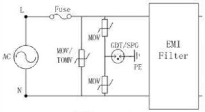
   Figure 1 Schematic diagram of common mode / differential mode protection circuit at AC input
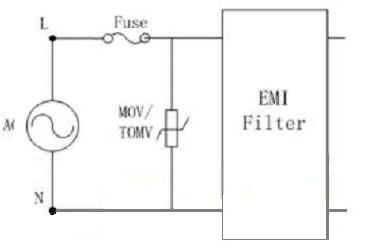
   Figure 2 Schematic diagram of the differential mode protection circuit at the AC input
In order to avoid the possibility of short-circuit failure ignition after the failure of the MOV protection component, TMOV or PMOV can be used for protection. For the above MOV AC withstand voltage selection, it should be at least 1.2~1.4 times higher than the maximum AC working voltage of the line to avoid malfunction. When using the discharge tube GDT/SPG at the same time, the lower limit of the breakdown voltage of the discharge tube must be at least Above the maximum peak voltage of the circuit, the withstand current must be selected according to the requirements of its own surge level to meet the requirements of the surge test standard.
2. Schematic diagram of protection circuit after AC/DC

   Figure 3 Schematic diagram of the protection circuit after AC to DC
After rectification of the AC, the chip in the back-end DC circuit is very sensitive to overvoltage and overcurrent, and the chip is susceptible to damage. As shown in Figure 3, after rectification, the parallel transient suppression diode TVS is used when overvoltage is generated. The TVS will operate at a picosecond response speed and clamp the over-voltage to a safe range to protect the back-end chip from overvoltage. The abnormal current can be protected by designing a self-recovering fuse PPTC in the circuit. The impedance of the PPTC can be rapidly increased when the overcurrent is generated, thereby effectively blocking the abnormal current until the PPTC is removed, and the low resistance state can be resumed, so that the circuit Can continue to return to normal working condition.
When the TVS is selected, the cut-off voltage is generally 1.2 to 1.4 times the peak value of the normal operating voltage. The TVS power size should be selected according to the energy of the overvoltage. The PPTC selection should be combined with the circuit operating current and voltage for reference and the ambient temperature is also an important key factor affecting the PPTC selection. The holding current of the PPTC will decrease as the ambient temperature of the application increases. The position of the PPTC in the circuit is generally connected in series with the TVS front end, so that the PPTC can not only effectively protect the circuit chip but also protect the TVS tube, which can greatly improve the service life of the TVS tube.
3, LED direct drive circuit protection diagram
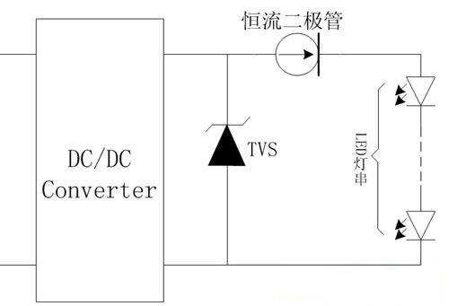
   Figure 4 LED DC drive circuit protection diagram
The brightness of LED illumination is controlled by the current through the LED. The unstable current is very easy to burn out the LED. As shown in Figure 4, after the DC/DC module, a constant current diode can be connected in series to obtain a stable current. It can make the LED achieve stable brightness without burning the LED due to the instability of the current. Low-power LED lamps typically operate at 10 mA to 30 mA. High-power LED lamps operate from 200 mA to 1400 mA. A suitable constant current diode can be selected based on the required operating current. Since the LED lamp is also vulnerable to the interference of the electrostatic discharge overvoltage, the LED lamp at the rear end of the DC/DC circuit also needs to perform a certain effective overvoltage protection, generally using a TVS tube.
4, LED light string protection diagram
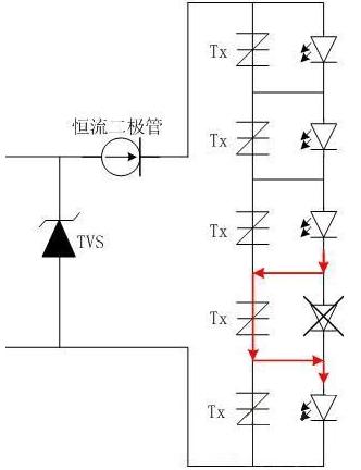
   Figure 5 LED bulb protection diagram
When a plurality of LED lights are connected in series, as shown in FIG. 5, once the LED lamp fails to open, the entire LED lamp will affect other LED lights due to the failure, in order to solve this problem, An anti-open LED protection device Tx can be connected in parallel with each LED lamp, so that the efficiency of each LED can be fully improved. When a single LED has a failure open circuit fault, the LED open circuit protection device Tx connected in parallel will immediately It is turned on, so that it can be maintained in an on-state state, thus ensuring that other series connected LEDs in the circuit are not extinguished due to an open failure of a single LED, but the cost of this protection is relatively high.
In summary, the LED driver circuit is generally composed of AC input, rectification, DC/DC conversion, and other modules, so that the overall protection scheme of an LED driver circuit can be referred to as shown in Figure 6:
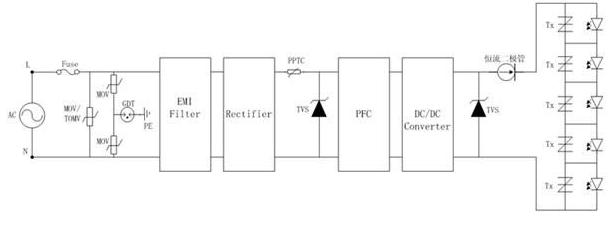
   Figure 6 Overall protection of LED driver power supply
When it is in practical applications, there are many factors that affect the selection of surge protection components. The lightning surge test level, chip parameters, operating voltage, and working environment are all issues that must be considered. Therefore, when designing protection for LED drive power, we need to consider many factors. Only by considering the comprehensive situation, we can design a protection scheme that can fully play its role.
The FirstPower gel battery uses the sealed gel technology and is designed for high reliable, maintenance-free power for renewable energy applications. Depending on the advantage gel technology, optimum grid and plate design, the FirstPower gel battery offers highest power and reliability for your equipments.
Industrial Gel Battery,Industrial Gel Cell ,Deep Cycle Industrial Gel Battery,Lead Acid Industrial Gel Battery
Firstpower Tech. Co., Ltd. , https://www.firstpowersales.com