Abstract: In order to solve the problem of unclear and unreasonable charges in the taxi industry, it is necessary to optimize the design of the taxi meter. Taking AT89C51 microprocessor as the core chip, it controls the DS1302 real-time clock system, AEE4 Hall sensing ranging system, button system, AT24C02 power-down storage system and digital display system respectively to achieve the purpose of intelligent pricing. At the same time, KEIL 51 was used for system software design and PROTEUS for system simulation. Finally, the actual model was debugged and tested, and the effect was good.
This article refers to the address: http://
0 Preface
As a unique means of transportation in urban transportation, taxis play an irreplaceable role in urban transportation operations. Taxi drivers are most concerned about the convenience of the operation data management of the meter, and passengers are most concerned about whether the taxi pricing is reasonable. In order to reduce unnecessary misunderstandings between taxi drivers and passengers, it is very important to design a meter that can be accurately priced and conveniently used.
Technology is constantly evolving, society is making rapid progress, and taxi pricing systems need to be continuously optimized. In this paper, the embedded single-chip AT89C51 is used as the main control MCU, and the multi-function taxi intelligent meter is designed. This meter can comprehensively calculate the price according to the actual situation, and display important information such as the time of travel, mileage and bus fare. It has the advantages of more complete functions, more stable system and more convenient use.
1 Overall design of taxi smart pricing system
The AT89C51 is used as the intelligent pricing system designed for the core device of the MCU. It is easy to use and sensitive. Its powerful control processing function and expandable function provide a good choice for the design circuit. With its I/O port and its multi-function control, the button control is used for split-screen display to realize basic passenger pricing and information display. The overall design block diagram of the system is shown in Figure 1.
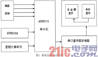
In the system hardware design, the AT89C51 single-chip microcomputer is used as the control center, and the external A44E Hall sensor signal acquisition module, clock module, button module, display module and power-down protection storage module are connected. Among them, the A44E Hall sensor signal acquisition module can be used to convert the magnetic induction into a pulse signal to measure the mileage; the clock module uses the DS1302 chip to set the standard clock; the power-down storage module uses the AT24C02 chip to ensure automatic data when the power is off. It is stored in the storage unit; when the system is powered on again, it can automatically read the data; the button module is controlled by four buttons, which can realize the split screen display function; the display module uses 8-bit LED digital tube for display.
2 system software design
2.1 system main program
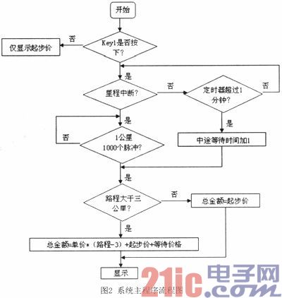
In the main program module, not only the initialization design of the parameters and interfaces, the setting of the taxi starting price and the unit price, but also the interruption, calculation and other operations need to be completed. The start/clear flag, mileage and price register should also be set and initialized. Finally, in order to achieve the integrity and accuracy of the contents of the register, the main program should be able to complete the operations of startup, clearing, metering and billing respectively.
When the taxi starts to run, the meter starts to start pricing at the same time, and calculates according to the stored data in the mileage register to determine whether the driving distance exceeds the starting price. If the starting price mileage has been exceeded, the current travel cost is calculated based on the mileage value, the unit price and the starting price; if there is no pulse input, there is no interruption if the waiting time exceeds the preset time. The waiting for the excess fee will be added to the total cost of the ride and the relevant information will be displayed. The main program flow chart of the system is shown in Figure 2.
2.2 System Module Program
The system module program mainly includes five service programs: display subroutine, mileage count interrupt, timed interrupt, midway waiting interrupt and button service program. The service procedures are as follows:
(1) Display subroutine. Since the split screen data display mode is adopted, four display subroutines are required: display of hour, minute, and second, display of unit price, display of distance unit price, and display of standard time.
(2) The mileage count is interrupted. The Hall sensor is interrupted every time a low level signal is output. When the mileage counter counts 1000 mileage pulses, the current count is sent to the mileage count interrupt service routine, and the current driving mileage and related data are transmitted to the driving mileage and In the ride fee register.
(3) Timed interruption. In the timer interrupt service routine, set the interrupt time to 50ms and the 20th interrupt time to 1s. After 1s, the data will be sent to the corresponding display unit for real-time display.
(4) Waiting for interruption midway. When the Hall switch has no signal output in the counting state, the on-chip timer starts. Each time the waiting time reaches 5 minutes, the midway waiting fee is automatically added to the current amount. After the waiting time, the pricing system automatically switches to the normal pricing procedure.
(5) Button service program. The button service adopts the query mode and is set in the main program. When no button is pressed, the MCU runs the main program cyclically; when the button is pressed, it turns to the corresponding subroutine and performs other operations.
3 system simulation and function realization
3.1 Introduction to Simulation Software Proteus
Proteus simulation software is an EDA tool designed and developed by Labcenter Electronics of the United Kingdom. It not only has the simulation function of other tool software, but also simulates microprocessors and related peripherals. Proteus software is powerful: with the Proteus electronic design tool, it is equivalent to building an electronic design and analysis platform. With the powerful Proteus simulation software, we can simulate the circuit to determine if the solution is feasible and the design process can be smooth.
3.2 Circuit Function Simulation
First, build the circuit through the Proteus platform, then write the corresponding code in KEIL, and load the generated HEX file in the Proteus platform microcontroller model, you can see the simulation effect.
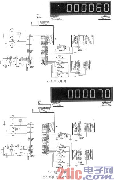
(1) Unit price simulation. According to the actual situation, the starting and operating prices are different during the day and night. Simulation experiments were carried out on day and night, and the simulation results are shown in Figure 3.
(a) unit price during the day (b) unit price at night
In Fig. 3, (a) is a daytime period, showing a starting price of 6 yuan during the day; and (b) is a night time period, showing a starting price of 7 yuan at night.
(2) Simulation of other relevant important parameters. In addition, simulation studies have been carried out on other major aspects of the pricing system (for the sake of discussion, the circuit part shown in Figure 3 is ignored, only the data part is displayed).
The simulation effect is shown in Figure 4. The details are as follows:
Display unit price, mileage and amount within 3 km and 3 km: Figure 4 (a) shows the distance is 2 km (within 3 km, within the starting price), the amount is 6 yuan; Figure 4 (b) shows the mileage is 22 Kilometers (3 km away), the unit price is 2 yuan, and the amount is 44 yuan.
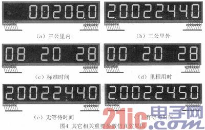
Display standard time and mileage time: Figure 4 (c) shows the current standard display time 08:20:28; Figure 4 (d) shows the ride time of 20 minutes and 28 seconds.
There is no waiting for simulation contrast effect: Figure 4 (e) is the price of no waiting time on the road; Figure 4 (f) is the price of waiting time on the road. According to the program setting plus 1 yuan every 5 minutes, it can be seen that there is waiting time on the road in Figure 4 (f), and the waiting time is 5 minutes.
(a) within three kilometers (b) three kilometers away
(c) Standard time (d) mileage time
(e) no waiting time (f) waiting time
By observing the above simulation results, it can be analyzed that the relevant information such as running unit price, riding mileage, driving time and total cost can be displayed on the digital tube, so the system design achieves the expected goals and requirements.
4 System experiments and results analysis
Weld according to the schematic diagram to ensure that the wiring is correct. The actual object is debugged and tested, and the final experimental result is shown in Figure 5.
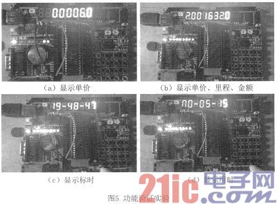
From the experimental results in Figure 5, we can see:
(1) Figure 5 (a) shows the unit price. Press button 1 to enter the passenger status and the unit price will be displayed.
(2) Figure 5 (b) shows the unit price, mileage and amount. In addition, when the power is turned off, the data is sent to the storage unit, and after the power is turned on, the relevant data before the power failure can be displayed, thereby achieving the power-down storage protection function.
(3) Figure 5(c) shows the standard time. Press the key 2 to view the standard time.
(4) Figure 5 (d) shows the time of driving. Press button 3 to view the driving time in real time.
The experimental results show that the AT89C51 master control, Hall sensor for acquisition, AT24C02 for power-down storage protection, coupled with the program, can better realize the taxi smart pricing function.
5 Conclusion
The taxi intelligent pricing system designed in the text can store relevant data in real time, and display the stored data through the 8-bit LED digital tube to realize the basic pricing function. The system considers the situation that may occur in the ride more comprehensively, and can adjust the unit price according to different situations such as daytime, nighttime, and midway waiting, thereby achieving the purpose of intelligent metering of the taxi. Of course, in order to achieve large-scale practical application requirements, it is necessary to continuously improve and improve the system's comprehensive performance indicators to meet practical application requirements.
LED outdoor wall lights are widely used in residential areas, tourist attractions, squares, parks, private gardens, courtyard corridors and other public places to illuminate. It not only effectively provides people with travel safety, but also has an important role in the construction of the entire comfortable environment. Function, during the day LED Outdoor wall lamp can embellish the city scenery, at night LED Outdoor Wall lamp can not only provide the necessary lighting, but also increase the residents' sense of security to interpret the bright style
Outdoor Wall lamp,IP67 Wall light,waterproof wall lamp,Wall lamp waterproof.Outdoor wall mounted light
SHENGYA LIGHTING TECHNOLOGY CO., LTD. , https://www.syalighting.com