As the OEM's product size requirements are getting higher and higher, to make the assembly size meet the product drawing requirements, the stamping parts and assembly manufacturing process need to be strictly controlled, and its control ability comprehensively reflects the product development and quality of a company. Control level. Shanghai Tractor Internal Combustion Engine Co., Ltd. (referred to as: Tone Company) combined with the characteristics of its own products, through continuous summarization and exploration to find a suitable size control method, that is, grasp the fundamental, control the product's source of variation.
This article refers to the address: http://
In the product development stage, there are four stages that will have a large impact on product size, namely product design, process development, trial production and mass production. The degree of impact and focus of each stage are different. To control the source of variation, the development phase control is 70% and the process control is 30%. Product design and process development are especially important during the development phase.
Rationality of product design
The product design should avoid the stamping and forming process being too complicated, reduce the stamping rebound and the interference of the parts. For the holes with relative assembly relationship on the stamping parts, try to punch in the same process as much as possible, and the important hole positions should be arranged in the same process as the positioning holes. The design of the mold fixture must be reliable. For example, the fixture positioning hole must select the main positioning hole for the stamping. The positioning surface must select the reliable surface of the stamping part. Once again, the tooling design should be easy for employees to pick and place materials, easy to operate and maintain, in order to prevent the size of the production process due to ergonomic problems. Finally, the punching hole diameter tolerance table is formulated, and the hole diameter and hole position of each stamping part are specified. The tolerance is 80% of the assembly required, and 20% is reserved for the assembly to ensure the assembly size pass rate.
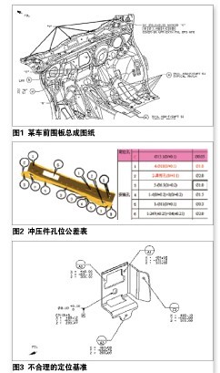
As shown in Figure 1, the position of five φ6.5 holes on a single piece of drawing is not specified. If the default tolerance of 2.0 is used, it is obviously lower than the requirements of the assembly 1.4, so even if the hole position of the part is within the tolerance, it is difficult to ensure the hole position requirement after welding, so we receive the hole tolerance of the stamping part. 1.0.
Rationality and integration of positioning benchmarks
To ensure part quality, the positioning criteria first meet the 3, 2, 1 principle. Some drawings seem to conform to the 3, 2, 1 principle from the surface, but the actual positioning is unreasonable. As shown in Fig. 3, A1, A2, and A3 all control the Z direction, but they are not in a plane. The face of A3 is both the positioning surface and the mating surface, even if the flange surface has rebound and tolerance, in the part inspection. It is also not easy to find. If the A3 is placed on the bottom surface more reasonable, it can effectively control the mating surface of the product.
Secondly, it is necessary to establish a vehicle body unified reference system for unifying the main positioning reference principle from stamping parts, parts inspection tools, welding assemblies, body-in-white assembly to final assembly, and establishing a MCP (Master Control Point) list for stamping, welding, and The final assembly process is coordinated during the development of the positioning tooling to avoid deviations due to different process positioning options. At the same time, it is also necessary to ensure that the measurement positioning reference is consistent with the positioning reference of the manufacturing fixture.
Fixture positioning method
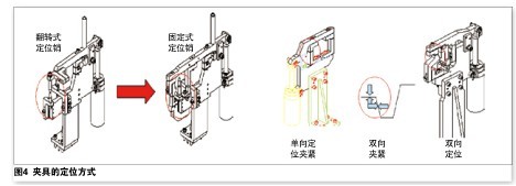
Considering the impact of sheet metal springback, irregular shape, material and stamping process, the welding fixtures are over-positioned to correct part deformation, and the positioning and clamping units are designed to be adjustable in three or two dimensions to accommodate part changes. . In addition to the over-positioning pin, the dragging company adopts a method of receiving tolerances on the positioning pin. The main positioning pin has a nominal size of -0.05 mm than the hole. For the B-pillar assembly, the A-pillar assembly, the inner and outer plates. The positioning of the pin is used during assembly to improve the stability of the tooling.
Before the trial production, the installation of fixtures is very important, only qualified tools can produce qualified products. After the fixture is in place, all measuring holes should be measured with a measuring device (such as a laser tracker) to establish a complete positioning reference data to facilitate product size coordination during production. With large size and complex parts as the guide, the remaining parts are then mounted on the fixture, that is, “positioning-clamping†one by one.
The trial production after the general tooling is in place needs to be maintained for 6 months to meet the quality control objectives of the different stages of production. The trial production stage is mainly to solve the matching and coordination of the actual parts and fixtures, and to solve the practical difficulties in the operation process, until the beats and quality objectives of the design requirements can be transferred to mass production.
Data collection and analysis
There are many ways to obtain product size data. The most common method is to use the three-coordinate measuring system, the inspection tool and other tools to detect the conformity of the actual part with respect to the design digital model, and then compare the tolerance points of each measurement point. And the qualification rate requirements to determine the yield of the product size.
Based on the data of the three-coordinate measuring system, the general complex assembly can obtain more than a few hundred and hundreds of product measurement point data, but one by one analysis is impossible and unnecessary. At present, the company's practice is to first count the status of the unqualified points, and then confirm and rectify the production process when the data is stable. It also pays attention to the out-of-tolerance situation and distribution of the unqualified points, and calculates the process capability (CP) of some assembly and customer-focused points that need to be controlled, and reflects the quality status of the entire product through the points represented by the part.
Product size change
Data collection and analysis can identify the problem and identify the root cause of the problem. Through the simple confirmation of the engineer, the influence of both the person and the method can be basically eliminated or corrected, and then the stamping piece is inspected by the inspection tool. At the same time, according to the results of the assembly data analysis, first check the positional accuracy of the welding fixture positioning surface and the positioning pin, record the deviation value and judge whether it is consistent with the trend of the problem, if it is first adjusted to the theoretical position. Next, place the part on the fixture, observe the corresponding condition of the part and the positioning surface and the positioning pin, and adjust to ensure that there is no interference between the part and the positioning surface. Again, check whether the part has a rotation or movement after positioning on the fixture, record the corresponding size of the positioning pin and the part hole, and combine the material detection data and the product size data analysis result to form corrective measures for the positioning pin and the surface. In principle, the material has problems to rectify the material first, and then rectify the machine (welding fixture), but in fact, as long as the material state remains stable, many product size problems are solved through fixture rectification, because the fixture rectification is relatively more efficient and more economic.
After the development and completion of the mass production, the materials and machines are relatively stable. At this time, as long as the state of the materials and the machine are regularly checked, the maintenance and stability are maintained in time, and the energy needs to be transferred to the execution of personnel and process methods. Management aspect. In the mass production phase, some positioning pins, loose surfaces and wear can be prevented by the SPC control chart.
Monocrystalline silicon Solar Panel is a kind of solar cell which is made of high purity monocrystalline silicon rod. Its structure and production process have been finalized, products have been widely used in space and ground. Monocrystalline silicon refers to the integral crystalline form of silicon material, which is a common photovoltaic power generation material. Monocrystalline silicon solar cells are the most mature technology in silicon-based solar cells. Compared with polycrystalline silicon and amorphous silicon solar cells, their photoelectric conversion efficiency is the highest. The production of high efficiency monocrystalline silicon cells is based on high quality monocrystalline silicon materials and mature processing technology. The monocrystalline silicon solar cell material is simple to manufacture, saves electricity consumption and the total production cost is low. Monocrystalline silicon solar cells have a long service life.
Monocrystalline Silicon Solar Panels
Monocrystalline Silicon Solar Panels,Monocrystalline Solar Panel Specifications,Monocrystalline Silicon Solar PV Panels, Monocrystalline Silicon Material Solar
ZHEJIANG FIZZ NEW ENERGY CO.,LTD , https://www.ywfizz.com