introduction
This article refers to the address: http://
The automobile tire pressure monitoring system (TPMS) is an early warning system that can automatically detect the tire pressure and temperature and alarm the abnormal condition of the tire. The TPMS system can be divided into indirect and direct. Indirect is to compare the speed difference between the wheels through the wheel speed sensor of the ABS system of the car to achieve the purpose of monitoring the tire pressure. The pressure sensor installed in each tire is directly used to directly measure the air pressure of the tire and is transmitted by wireless modulation to a receiver mounted on the bridge [1].
At present, the direct TPMS transmitting module mostly adopts the following two schemes: one is battery + single chip + sensor + radio frequency chip, and the other is battery + internal integrated MCU (micro controller) sensor + radio frequency chip. The former solution was gradually phased out due to low integration, size and power consumption. The latter solution is the mainstream product design form on the market today. Because the amplitude shift keying (ASK) signal modulation mode has the advantages of low power consumption, high sensitivity and low cost, this paper selects the MAX7044 based on ASK mode as the transmitting chip, and Infineon's SP30 as the sensor design completes a new type of tire. Pressure transmitter module.
Transmitter module hardware design
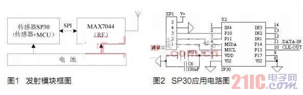
The transmitter module hardware is mainly composed of sensors SP30, MAX7044, battery and antenna, as shown in Figure 1. The sensor SP30 of the internal integrated MCU sends data to the MAX7044 through the serial communication interface, and the battery supplies power to both. The operating temperature of the device selected in this design is automotive grade (-40 ~ +125 ° C), to meet the requirements of reliable operation in the complex and harsh environment of the tire launch module. The program follows European standards and the center frequency of the wireless signal modulation is 433.92 MHz.
SP30 application design
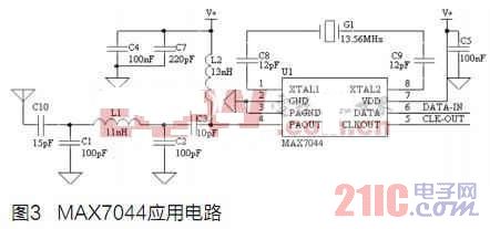
SP30 is a special sensor chip for tire pressure detection introduced by Infineon. It not only has pressure, temperature, acceleration and battery voltage sensors, but also integrates an 8-bit Harvard RISC microcontroller with operating voltage range of 1.8~3.6V. The range is 0~3.5Bar, the temperature measurement range is -40~+125°C, and the application circuit is shown in Figure 2 [2]. There are very few SP30 peripheral devices, only need to connect a 3V battery and filter capacitor.
The SP30 operates in four modes, low power mode, idle mode, operating mode, and thermal shutdown mode. Among them, the low power mode consumes the least power, so the SP30 should be in this working mode as much as possible to ensure a long battery life. P14 and P15 are serial communication ports, P14 is serial data, P15 is the external clock provided by MAX7044, the clock frequency is 847.5kHz, P17 is useless grounding. XP1 is the debug interface.
MAX7044 RF Application Design
The wireless transmitter chip is the key to the reliable operation of the transmitting module. Since the transmitting module is mounted on the hub and powered by a lithium battery with limited energy, the selection of the transmitting chip needs to have the following two characteristics:
â— Low power consumption, ASK modulation support, multiple working modes, easy to manage power consumption according to specific working conditions, to maximize battery life;
â— The chip has a minimum operating voltage and a large enough transmit power.
Based on the above characteristics, and after analysis and comparison, we finally chose the MAX7044, a cost-effective transmitter chip.
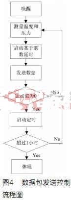
The MAX7044 is an ASK modulation chip from the 300MHz to 450MHz frequency range produced by Maxim. The maximum output power is +13dBm (50Ω load). The supply voltage is at least 2.1V. The low-power mode current is only a few tens of nanoamps. The internal power amplifier is integrated. Circuits such as crystal oscillators and phase-locked loops are designed in an 8-pin SOT23 package [3]. The application circuit is shown in Figure 3. It mainly includes three parts: power supply decoupling circuit, crystal oscillator circuit and antenna matching circuit. Since the RF (radio frequency) chip is very sensitive to the noise of the power supply, an appropriate and effective power supply decoupling circuit can suppress noise and improve reliability, so the decoupling capacitor C5 is disposed near the 3V power supply pin. The MAX7044 commonly used modulation frequencies are 315MHz and 433.92MHz, and the crystal oscillators used for different modulation frequencies are also different. The relationship between the modulation frequency fRF and the selected crystal frequency fXTAL is: fXTAL=fRF/32. The modulation frequency of this design is 433.92MHz, then the external crystal frequency G1 should be 13.56MHz, and the output frequency CLK-OUT is the crystal frequency divided by 16 or 847.5kHz. The output frequency CLK-OUT is used to provide operational timing to the microcontroller inside the pressure temperature sensor SP30. The output impedance of the MAX7044 power amplifier (PA) is 125Ω. To match the antenna of a specific impedance, an impedance conversion circuit must be configured to reduce the transmit power loss and improve the antenna performance. This design uses a valve as the antenna, C10 is used to offset most antenna inductive reactance, C1, C2 and L1 form a low-pass filter, which can suppress the higher harmonics of the PA output. L2 is used to suppress RF interference from the power supply, and C3 is a DC blocking capacitor [4]. Through software simulation and repeated test verification, the best matching circuit is shown in Figure 3.
Transmitter module software design
Because the space and weight of the tire are limited, the transmitting module can only be powered by a miniature battery with limited capacity. Therefore, it is necessary to consider how to save energy for a single transmitting module with a life of more than 2 years. In addition, at least one transmitting module is not required for a spare tire in a car. Since the receiver cannot receive multiple wireless signals at the same time, if the transmitting module simultaneously transmits data to the receiver, data collision will inevitably occur, resulting in failure of reception and The power consumption increases, so how to avoid sending conflicts is another key problem that software algorithms have to solve.
The data frame format adopted in this design is shown in Table 1. The preamble and stop bits are used to identify the start and end of a frame of data. The device ID is the globally unique identifier for the tire launch module to distinguish between different tires. The status information includes the battery-powered condition (SP30 has low-voltage detection) and the sensor measures the fault condition, and the checksum is used to check the correctness of the data transmission.
2 How to avoid sending conflicts
In the design we use a dynamic delay algorithm based on prime numbers. When a valid acceleration signal is detected, the four tire firing modules are woken up and the pressure and temperature detection procedures are initiated. After the data detection is completed, the dynamic delay is performed according to the prime number. After the delay time is reached, the data is sent out again. After the transmission is completed, the transmitter is automatically turned off, and a new round of data detection is started. The delay parameters of each tire are configured as follows: the delay of the left front tire launching module varies according to the period of 250ms×N1 (N1=2,19), and the delay of the right front tire launching module changes according to the period of 250ms×N2(N2=3,17), left rear The delay of the tire launching module varies according to the period of 250ms×N3(N3=5,13), and the delay of the right rear tire launching module changes according to the period of 250ms×N4(N4=7,11), and N1, N2, N3 and N4 are different respectively. Prime number [5]. This algorithm based on prime dynamic delay can effectively avoid the transmission conflicts of each transmitting module, reduce energy consumption and extend battery life.
3 How to save energy
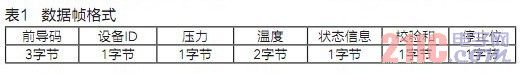
Since the transmitting module collects data and transmits data frames with the largest power consumption, the transmission frequency and the number of data frames transmitted each time should be reduced as much as possible while ensuring the correct data transmission. The software flow of the transmitting module is shown in Figure 4. The SP30 integrates an accelerometer. When it detects that the vehicle has been inactivity for more than 1 hour, it automatically enters the low-power sleep mode (current is micro-ampere). At this time, data detection and transmission are no longer performed. When the car moves, the acceleration signal wakes up the transmitting module. After the data acquisition is completed, the dynamic delay algorithm based on the prime number is started, that is, the data is transmitted after the delay of 250ms×N (N is a random prime number less than 20). The actual test shows that the flexible switching of the working mode and the reduction of the transmitting frequency can effectively control the service life of the transmitting module.
Performance Testing
This design has been applied in product design. The specific performance indicators after repeated testing are as follows:
â— It can monitor the tire pressure range from 0 to 3.5 Bar and the resolution is 25mBar. Usually the tire pressure of the car is between 2.2Bar and 2.8Bar.
◠The temperature range can be monitored: -40 ~ 125 ° C, the resolution is 2 ° C, the tire temperature of the car is generally around 75 ° C;
â— The radiation power of the tire pressure sensor is measured at -45dBm with a spectrum analyzer;
â— With 500mAh battery, if the vehicle is driving for 12 hours every day, the transmitter module can work normally for more than 5 years.
Conclusion
This paper designs and implements a direct tire pressure monitoring system launch module. Based on the SP30 sensor and the MAX7044 transmitter, the transmitter module has high integration and small size, and can simultaneously monitor three key parameters of tire pressure, temperature and battery voltage during vehicle driving. When the tire has abnormal conditions such as air leakage, over-pressure and over-temperature, it can automatically alarm in time to ensure driving safety.
EDM (electrical discharge machining), is a manufacturing process used to obtain a specific desired shape in metal by applying electrical discharges(sparks),When it comes to using electrical discharge machining, the water serves as a key component. To get the best performance from an Edm Machine, the water must be kept as clean as possible. During the EDM process, some of the metal goes into the water as small particles. The water is filtered and deionized(demineralized) in order to remove those metal atoms. Deionized water helps to promote a higher metal removal rate and enhances the machine`s capacity to deliver a more precise cut. So the EDM water filter is very important component for EDM water filtration system.
Edm Filter,Edm Machine,Edm Machining,Wire Edm Machine
Donguan Bronco Filter Co., Ltd , https://www.broncofilter-cn.com