The characteristics of the electrical control products of the needles are discussed. The design methods of the common input/ output circuits of several single-chip microcomputers are discussed. It has practical guiding significance for rationally designing the electrical control system, improving the interface capability of the circuit, and enhancing the stability and anti-interference ability of the system.
introduction
The various control signals used in conventional electrical equipment must be converted to digital signals that match the input/output ports of the microcontroller. The user equipment must input various control signals to the single-chip microcomputer, such as limit switches, operation buttons, selection switches, travel switches, and other switching outputs of the sensors, etc., and convert them into signals that can be received and processed by the single-chip microcomputer through the input circuit. The output circuit should convert and amplify the weak electric control signal sent by the single-chip microcomputer to the strong output signal required by the field to drive the actuators of the power tube, solenoid valve and relay, contactor, motor and other controlled devices, which can facilitate the actual control system. .
1 input circuit design
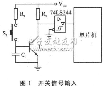
Generally, the input signal will be input into the MCU in the form of a switch. From the engineering experience, the effective state of the control input of the switch input is much better than the high level effect, as shown in Figure 1. When the switch S1 is pressed, the command signal sent is low level, and when the switch S1 is not pressed normally, the level outputted to the single chip microcomputer is high level. This method has strong noise resistance.
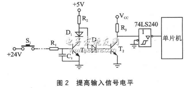
If it is considered that the TTL level voltage is low and it is susceptible to external interference in long-line transmission, the input signal can be increased to +24 V, and the high-voltage signal is converted into a TTL signal at the entrance of the microcontroller. This high-voltage transmission method not only improves the noise resistance, but also makes the contact of the switch contact good and reliable, as shown in Figure 2. Among them, D1 is a protection diode, and the reverse voltage is ≥50 V.
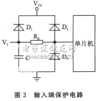
In order to prevent external spikes and static electricity from damaging the input pins, an anti-pulse diode can be added to the input to form a resistor bidirectional protection circuit, as shown in Figure 3. The forward voltage drop UF 二æžç®¡ 0.7 V of the diodes D1, D2, and D3, and the reverse breakdown voltage UBR ≈ 30 V, the protection circuit can limit the amplitude of the 浚 voltage to no matter what kind of polarity breakdown voltage occurs at the input end. The input can withstand the range. That is: when a positive pulse occurs from VI to VCC, D1 is forward-conducting; when a negative pulse occurs in V1 to VCC, D2 reverse-breaks; when a positive pulse occurs between VI and ground, D2 reverse-breaks; between V1 and ground When a negative pulse occurs, D3 is forward-conducting and the diode acts as a clamp. The snubber resistor RS is about 1.5 to 2.5 kΩ, and constitutes an integrating circuit with the input capacitor C, and delays the external induced voltage for a period of time. If the interference voltage is less than t, the effective voltage on the input will be much lower than its amplitude; if the time is longer, D1 will be on. The current creates a certain voltage drop across the RS, which reduces the input voltage value.
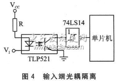
In addition, a common input method is to use an optocoupler isolation circuit. As shown in Figure 4, R is the input current limiting resistor, limiting the LED current in the optocoupler to 10-20 mA. The input is coupled by an optical signal and is electrically isolated completely. At the same time, the forward resistance of the LED is low, and the internal resistance of the external interference source is generally high. According to the principle of voltage division, the interference noise that the interference source can feed to the input terminal is small, and no ground interference or other crosstalk is generated. Enhanced the anti-interference ability of the circuit.
Under the premise of satisfying the function, the simplest solution to improve the reliability of the input end of the single-chip microcomputer is to connect a capacitor in parallel with the input terminal to ground to absorb the interference pulse, or connect a metal film resistor in series to limit the peak current flowing into the port.
The FirstPower High Rate Discharge Battery is desgined for apllcation as High Rate Discharge. This series is a high energy, high intensity, and high quality output electrical energy product series with 20% more energy density than same volume products at high rate discharge characteristics.
We welcome orders with "FirstPower" brand; We are also flexible to accept orders on OEM basis. Contact us now! Your partnership with FirstPower will prove worthy of it.
High Rate Discharge Battery
High Rate Discharge Battery,High Discharge Rate Lipo Battery,Smart High Rate Discharge Battery
Firstpower Tech. Co., Ltd. , https://www.firstpowersales.com