At present, the leakage protector as a new type of low-voltage protection appliance is very common in urban or rural installations, and its reliability directly affects personal safety. In the United States, it is a mandatory safety protection device implemented by the government and must be replaced every two years. Although the use of leakage protectors in China does not impose a mandatory replacement period, from the perspective of electricity safety, regular inspection of the performance of the leakage protector is necessary. This paper introduces the automatic tester for the action characteristics of the leakage protector, which can measure and record the contact breaking time, leakage current and non-operating current of the leakage protector, and provide important technical indicators for improving the working performance of the leakage protector. It can detect leakage protectors running online and offline.
1 hardware design
The main three parameters reflecting the leakage performance are: rated leakage current (Iâ–³n), leakage operation time and rated leakage non-operation current (Iâ–³n0).
Iâ–³n characterizes the sensitivity of the leakage operation and is the leakage current value of the leakage protector. The leakage operation time is the time required to apply a leakage current to the circuit breaker to cut off the circuit. Iâ–³n0 is the leakage current value that prevents the leakage protector from malfunctioning, and the non-operating leakage current value specified by the national standard is usually 0.5Iâ–³n.
The method of testing the leakage current is: applying a test current from less than 0.2I?n, linearly increasing to I?n within 30s, if the current value of the leakage protector is I?, when I?n0n0 is satisfied Iâ–³ "Iâ–³n, the leakage current of the leakage protector is acceptable. Therefore, the uniform increase in the leakage current value of the test will directly affect the accuracy of the measurement. The use of conventional manual and motor-driven voltage regulators makes it difficult to evenly increase the current value of the test leakage, making it difficult to control the random error of the measurement. The single-chip microcomputer is used to control the current value of the leakage in real time, so that the leakage current is evenly increased, which can effectively improve the accuracy of the measurement. Figure 1 shows the block diagram of the leakage protector operating characteristic tester.
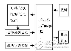
Figure 1 Tester block diagram
The tester uses the ATmega32 microcontroller as the core to expand the programmable leakage current source, leakage current detection circuit, contact state monitoring circuit, keyboard and display peripheral equipment. ATmega32 is an 8-bit microcontroller based on the enhanced AVR RISC architecture. The instruction set is advanced. The instruction execution time is single clock cycle, and the speed is 8~12 times that of the ordinary 8051 microcontroller. Operating frequency up to 16MHz, on-chip 32K bytes of Flash program memory, one hardware 16-bit timer and two 8-bit timers, four PWM outputs, eight A/D conversions, one full-duplex asynchronous serial port 32 general purpose I/O ports. It has the advantages of low power consumption, high speed, super strong anti-interference, etc., and has high cost performance in similar products.
1.1 Programmable leakage current source
The key to ensuring measurement accuracy is that the programmable leakage current source can generate a uniformly varying leakage current. The leakage current source is composed of a 50 Hz sine wave generator and an AC quantity conversion circuit.
1.1.1 50Hz sine wave generator
The 50 Hz RC sine wave oscillator circuit consists of an operational amplifier. The amplitude of the stable oscillating signal is nonlinear negative feedback. At the same time, the resistor and capacitor of low temperature coefficient are used to form the frequency selection circuit of the RC sine wave oscillating circuit to ensure the stability of the oscillating frequency. In order to improve the load capacity, the sine wave output The signal is output through a voltage follower.
1.1.2 AC digital-to-analog conversion circuit

Figure 2 AC digital-to-analog conversion circuit
The AC digital-to-analog conversion circuit is the core part of the programmable leakage current source. The amplitude of the sinusoidal AC quantity is controlled by changing the digital quantity and has good linearity. A digital-to-analog conversion circuit is constructed using DAC08 08, which is a binary fast multiply 8-bit D/A chip. The AC digital-to-analog conversion circuit is shown in Figure 2. In order to ensure the digital to sinusoidal AC analog signal transition, VD is a preset DC bias, the magnitude of which is equal to the design of the 50Hz sine wave generator output signal leakage protector intelligent tester.
According to the circuit shown, the following relationship can be obtained: 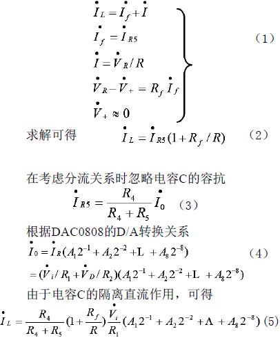
It can be seen from equation (5) that when the resistors R1, R4, R5, R, and Rf are constant values, the magnitude of the output current is independent of the RL and is controlled only by the digital amount. When A1, A2, ..., A8 are all "1", adjust the circuit parameters so that IL = 0.5A. When A1, A2...A8 are all "0", make the current variation range of IL=0A.0~0.5A. It fully meets the testing requirements of the current leakage protector produced in China. In order to improve the measurement speed, the output current is divided into four steps of 50mA, 100mA, 200mA and 500mA under the condition of ensuring the accuracy of the simulated leakage current. The selection of each gear is realized by the size of the ATmega32 switching resistor R1. In different gears, the magnitude of the current increase is not the same. When the 50mA gear is selected, the current is incremented by 0.196mA (50mA/255); when the 500mA gear is selected, the current is incremented by 1.96mA (500mA/255), so it can fully satisfy the linear increase of the leakage protector. Leakage current requirements.
1.2 contact status monitoring circuit
The contact state monitoring circuit is shown in Figure 3. When the dynamic and static contacts of the leakage protector are closed, the AC power of L1 and L2 is rectified, filtered and stabilized, so that the photocoupler G3 is turned on, and the output of the 2 pin of the inverter A is high. When the dynamic and static contacts of the leakage protector are disconnected, the photocoupler G3 is turned off, and the output of the inverter A is low, as the time at which the leakage detection ends. When the dynamic and static contacts of the leakage protector are closed, the current of the photocoupler G3 passes through a phase and static contact of the leakage protector, and the current is 1~2 mA. Since it is DC, it will not be in the leakage protector. The secondary side of the zero-sequence current transformer generates an induced current, which has no effect on the leakage current of the leakage protector.
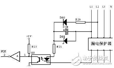
Figure 3 contact status monitoring circuit
1.3 control circuit
The control circuit is shown in Figure 4. The start signal generated by the leakage current of the leakage protector is controlled by the program, and the dynamic and static contact disconnection signals are sent to the external interrupt input terminal PD2 of the ATmega32, and the breaking time of the dynamic and static contacts of the leakage protector is detected by means of interruption. . The button S1 is selected as a test function to select the measurement of the leakage current or the leakage operation time. The button S2 is used to select one of the analog leakage currents of 50 mA, 100 mA, 200 mA, and 500 mA. The buttons S3 and S4 are used to set the current value of the analog leakage when measuring the leakage operation time, S3 controls the current value of the analog leakage, and S4 controls the current value of the analog leakage to decrease. S5 is the test start/stop control button. When measuring the leakage current, set the parameter to press S5, ATmega32 according to the gear output data selected by S2, so that the analog leakage current increases from 0 to the maximum value. If the simulated leakage current reaches a certain current value, the leakage protector operates. Then the current value is the actual leakage current value. When testing the leakage operation time, set the leakage current parameter and press S5. ATmega32 directly generates the set analog leakage current according to the set current value to realize the measurement leakage operation time.

Figure 4 A / D conversion and control circuit
2 software design
Based on the embedded C language design of the ATmega32 software part, the program structure is modular. Specifically, the main program, the instrument initialization subroutine, the function control subroutine, the programmable leakage current source subroutine, the detection leakage operation time subroutine, and the display subroutine are included.
The main program is the main control program for detecting the operating characteristic parameters of the leakage protector. When the tester is working, the main program runs cyclically, and the relevant subroutine is called according to the function requirement, and the subroutine returns to the main program after execution. The instrument initialization subroutine realizes the initialization of the instrument, including instrument parameters, microcontroller pin configuration, timer, analog-to-digital conversion, and interrupt initialization. The control function subroutine realizes the scanning of the button functions and controls the communication between the instrument and the person. The programmable leakage current source subroutine is used to generate the leakage current for testing and to detect the current value (Iâ–³) of the leakage current when the leakage protector is disconnected. The detection of the leakage operation time subroutine realizes the detection of the leakage action time of the leakage protector. The subroutine is displayed to display the leakage current and the leakage operation time.
3 Conclusion
The tester is simple in operation, solves the problem of inaccurate measurement in the manual test method, achieves the purpose of automatic measurement, can detect the leakage protector running online and offline, and improves the performance of detecting the leakage protector for the purpose. The research, quality inspection and production debugging of the leakage protector provide technical means. The instrument design makes full use of the various functions built into ATmega 32, which makes the hardware circuit structure simple and effectively improves the cost performance of the instrument. It has been used in many enterprises and scientific research units. The results show that the instrument works reliably and achieves the expected technical indicators.
Click to enter the expert online Q & A: LED drive power innovation technology
Corn Sheller,Hand Corn Sheller,Corn Sheller Machine,Hand Crank Corn Sheller
Hunan Furui Mechanical and Electrical Equipment Manufacturing Co., Ltd. , https://www.thresher.nl