Compared with electric vacuum power devices, microwave solid-state high power amplifiers have the advantages of small size, low operating voltage, good frequency bandwidth, good linearity, high reliability, long life, simple structure and easy maintenance. Microwave communication, radar, electronic countermeasures, telemetry and remote control and other electronic systems have a wide range of applications to complete the amplification of weak signals. In order to make it have higher efficiency, better performance and lower failure rate in practical applications, this paper takes its application in FY-2E meteorological satellite as an example to study its design and key technologies, combined with practice Finally, several targeted and effective protective measures were proposed.
Design idea of ​​single-stage amplifier circuit
The design of the general microwave power transistor amplifier mainly includes: according to the required performance index, the working state is determined, the input and output matching circuit design, the bias circuit design, and the thermal design. Figure 1 shows a typical common base transistor amplifier circuit.
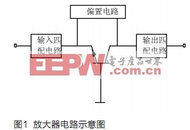
The power amplifier of FY-2E adopts Class C operation and saturates output. In general, the amplifier is most efficient when it is operating at or near saturation. However, since working in a non-linear state, when determining the operating point, in addition to considering efficiency, the requirements of non-linear distortion should also be considered. The input-output matching circuit [1-3] here mainly matches the load impedance with the source impedance, reduces power reflection loss, increases transmission power, reduces noise interference, and improves the linearity of frequency response. The design idea has the following two options: 1. Use the analytical method to find the value of the circuit element. This method can get very accurate results and is suitable for computer simulation; 2. Use Smith's original image as a graphical design tool. This method is relatively less computational, more intuitive and easy to verify. The function of the bias circuit is to provide an appropriate static operating point, and to suppress the dispersion of crystal parameters and the effect of temperature changes to maintain a constant operating characteristic. Generally, a passive bias network is easy to implement, but it is not as flexible as an active bias network. Its design considerations include efficiency, noise, suppression of oscillation, independent power supply, RF choke, and impedance matching.
Design and key technology of FY-2E medium solid state power amplifier
The main performance indicators of solid-state power amplifiers are: operating bandwidth, gain, gain flatness, stability, third-order intermodulation, and input-output voltage standing wave ratio (VSWR). Single-stage amplifiers are difficult to meet the design requirements due to the limitations of working state, linearity, process, etc. In practice, the power is generally synthesized in parallel with multiple tubes. The solid-state power amplifier in the ground application system of the FY-2E meteorological satellite adopts a synthesis method of four tubes in parallel (see Figure 2).
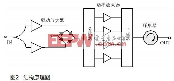
The system is mainly composed of drive amplifier, power amplifier and four-way waveguide power combiner. The drive amplifier works in the form of 1: 1 hot backup. Once one of the tubes has problems, it can automatically switch to the other backup amplifier to ensure the normal operation of the operation. The driving amplifier is divided into 4 channels by a splitter to promote the work of the power amplifier tube module. Finally, the four channels are combined to the waveguide power synthesizer for output. The function of the circulator is to prevent the reflected power from being too large and destroying the power amplifier tube when the standing wave is abnormal. Effect of transistor damage on the output of power amplifier components
Because the FY-2E system has completed an average of at least 28 cloud images per day 365 days a year, the high workload of 48 cloud images during encrypted observation during the flood season. Therefore, the stability and reliability of the power amplifier system is particularly important. If the transistor in operation is damaged, the component gain will be reduced. Let the gain change be W, and the number of transistors here is 4. Assume that the output field strengths of the four transistors are added in equal amplitude [4], so that the field strength of the total output signal of the synthesizer is 2E, and the power of the output signal is. When there are n-way transistors damaged in the 4-way, the field strength of the ground signal output by the synthesizer is and the power is, then the gain is. It can be calculated that when n = 1, the gain decreases by 2.5dB; when n = 2, the gain decreases by 6dB; when n = 3, the gain decreases by 12dB. We require a total gain of 60dB when the system is working, which shows that the stability of the solid-state power amplifier tube is considerable.
Impedance matching of transistors in power amplifier components
When the pulse is working, the transistor amplifier working in the Class C state has to go through the cut-off region, the linear region and the saturation region. Its input and output impedances change dynamically, but the characteristic impedances of the synthesizer and transmission line are generally fixed. Therefore, to obtain a good impedance match, the input and output impedance of the transistor must be transformed within the operating frequency band. The circulator at the rear can isolate the power amplifier component and the antenna feed part. Here, the output impedance of the power amplifier tube only needs to match the input impedance of the radial waveguide synthesizer. Commonly used transistor power amplifier matching network design methods include dynamic impedance method, large-signal S-parameter method and load pulling method.
Heat dissipation design of power amplifier components
Theoretically, the main factors affecting the stability of solid-state power amplifier components are temperature and operating frequency band [5]. When the working wavelength and the size of the feeder of the microwave circuit are comparable, it is easy to cause signal feedback, self-oscillation occurs in the working frequency band of the amplifier, and capacitance and inductance in the power supply feed line also easily cause low-frequency signal feedback. Because the FY-2E weather satellite operates in the S-band, the operating wavelength is relatively long, and the frequency stability is relatively good. And its daily high-intensity workload will produce high heat, causing the transistor temperature to rise sharply. Therefore, in order to ensure the stable operation of the solid-state power amplifier, the power amplifier tube must be thermally designed to ensure that the amplifier is in a stable working temperature range. At present, the heat dissipation work of the power amplifier component is mainly to transfer the heat generated by the transistor die to the flange of the transistor and then to the radiator. Through the air cooling system, a certain wind pressure is generated, so that the surrounding air takes away the heat from the radiator .
Application of solid state high power amplifier in FY-2E
FY-2E Meteorological Satellite Application System Ground Command and Data Receiving Station (CDAS for short) is mainly composed of antenna, channel, image, telemetry remote control, ranging and other sub-systems. The channel sub-system is one of the important components. The main task is to receive the satellite original cloud image, widened cloud image, telemetry, three-point ranging and other signals, and transmit the widened cloud image, remote control commands, three-point ranging and other signals. The solid-state power amplifier component is the throat of the channel system. It is also the device with the largest volume, the most power consumption, and the highest heat density in the system. Due to its high frequency band (China's meteorological satellite FY-2 series is in the S band), Whether the transmission network is well-matched requires high requirements, so its working characteristics will directly affect the performance index of the entire CDAS system.
Troubles and solutions during operation
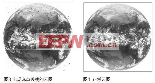
A satellite cloud image received in December 2009 was found. As shown in Figure 3, a large number of pits and line loss occurred, with a bit error rate of 10-3 orders of magnitude (normally ≤10-6), and the received The AGC level of the telemetry signal, the remote control command sent to the satellite, and the SSD tracking of the DPL are all correct, so it can be located that the channel part must have strong interference. Then check the operation of some channel equipment, and find that the problem is in the solid-state power amplifier. Its output power is 47dBm, and the reflected power reaches 43dBm. According to the formula: reflection coefficient, standing wave, the standing wave ratio can be calculated to be 4.4, which has greatly exceeded the normal value. 1.3. The cause of such a large standing wave ratio was studied and investigated, and it was found that the weather has changed drastically recently, the temperature has dropped, the snow is flying, the air humidity is high, and the inflator has started more times, and the desiccant has become red and failed, which is judged to be a waveguide system Air leakage, the humid air in the equipment room can not be dried very well, directly charged into the antenna feeder, and the feeder condenses and forms ice cubes outside, which causes the transmission network impedance to be mismatched, and the standing wave ratio exceeds the standard, which causes strong interference to the received signal. . In response to this situation, we cooperated with the equipment manufacturers to completely clean up the humid air in the waveguide and add a gasket at the waveguide interface. After processing, the output power is 46dBm, the reflected power is 28dBm, the standing wave ratio is normal, and the normal cloud image received is shown in Figure 4.
Solid-state power amplifiers are microwave devices that are extremely sensitive to the standing wave ratio. If the standing wave is too large, the working frequency band will become smaller, it will cause strong interference to the receiving part and saturate it, or even burn the transmitter. In order to prevent future problems, the author combines theoretical research with his work practice, and proposes the following major key regulatory measures.
Whether the standing wave of the solid-state power amplifier is good or bad depends on whether it is well matched with the back-end feeder network. Since most feeders work outdoors for a long time, they are easily affected by changes in ambient temperature and humidity, and rust and deformation caused by collisions in windy weather, resulting in large reflection losses. For this reason, it is necessary to ensure that there is no collision when the iron tower on the feeder is fixed, and it should be fixed firmly so as not to bear too much hard force, and the fixed spacing should not be too large; and in the case of sudden changes in ambient temperature and humidity, strengthen supervision and take protective measures; Regularly check the desiccant in the inflator to prevent it from becoming red and failing.
Put the power amplifier rear feeder network system into the scope of monitoring and management and set up monitoring points. Since the feeder inflator generally has a remote signal interface, it can collect and transmit the changes of the inflation pressure, inflation times, inflation time interval and other parameters to the network monitoring system, that is, Can be monitored in real time.
The solid-state power amplifier components of the FY-2E ground application system are mainly composed of input / output components, power amplifier modules, high-current power components, air-cooled systems, and power amplifier monitoring, control, and protection circuits. Sampling and testing of RF signal input and output power and reflected power. RF microwave tubes have high requirements on working conditions, so it is necessary to monitor the environment temperature, the temperature of each power amplifier module, power supply voltage, input power, output power, reflected power and other parameters in real time and implement rapid protection. In addition, when the power amplifier is working, the power is large and the heat is generated, so the air cooling system should be regularly inspected to ensure that the system is properly ventilated and cooled.
Conclusion
In this paper, through the discussion of solid-state power amplifier design ideas, key technologies and application examples, the effect of transistor damage on the output of the power amplifier component, the impedance matching of the transistor in the power amplifier component, and the heat dissipation design of the power amplifier component are studied. Several targeted and effective protection measures are proposed to improve the stability, reliability and efficiency of solid-state power amplifiers in actual business.
Home Appliance Heating Film apply to all aspects of our daily life.Such as mirror defog system ,health care for boby warming,far infrared heating health therapy,food warming tray,plant seeding propagator tray,wall mounted panel heater, heating element for electric heater,ceramic tile floor heating elements and so on.Overall,heating film is widely used in our Household life.What we supply is not only the good quality of manufactured goods but also offer service of custom-made heating film.We look forward to build business cooperation with customers worldwide.
Home Appliance Heating Film
Heating Film For Home Appliance,Home Infrared Heating Film,Home Heating Appliance,Home Appliance Heating Film
ShenZhen XingHongChang Electric CO., LTD. , https://www.xhc-heater.com