1 Introduction
TLV320AIC23 is a high-performance stereo audio codec launched by TI. It has a built-in headphone output amplifier and supports mic and line in input options. Both input and output have programmable gain adjustment function. TLV320AIC23's analog-to-digital converter (ADC) and digital-to-analog converter (DAC) are integrated in the chip. It adopts advanced Σ- △ oversampling technology. It can provide 16bit, 20bit, 24bit and 8bit at a sampling rate of 8kHz to 96kHz. 32bit sampling data. The output signal-to-noise ratio of ADC and DAC can reach 90dB and 100dB respectively. Simultaneously. TLV320AIC23 also has very low power consumption (playback mode is 23mW. Power saving mode is 15μw). The above-mentioned advantages make TLV320AIC23 a very ideal audio codec, which complements TI's DSP series.
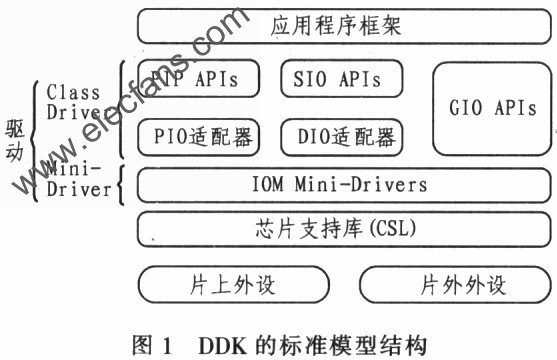
DSP / BIOS Driver Developer's Kit (DDK) is TI's driver development kit for TMS320 series DSPs and their EVM boards for simplified driver development. This kit provides a complete standardized driver model for various peripheral devices of the TMS320 series, so that the driver can be easily ported to other applications, greatly improving the efficiency of driver development. DDK is a supplement to the Chip Support Library (CSL) provided by each TMS320 series DSP. CSL provides low-level control of peripheral device register configuration and initialization. DDK completely controls peripheral devices through CSL. general speaking. DDK is built on top of CSL. So using DDK to develop drivers will be faster and more portable.
DDK defines a standard model and a series of APIs for developing drivers. To simplify program design. The standard model is divided into two levels. The upper level is called Class driver and the lower level is called Mini-driver. Class drivei is relatively independent from the device. It completes functions such as buffer management and request synchronization. It also plays the role of interface with both API and Mini-driver. Mini-driver completes specific device initialization and control functions. It conforms to the IOM (I / O Mini-driver) interface standard. This layered structure of DDK allows driver developers to understand the single Mini-driver API to complete the drive design of the entire peripheral device, and this process is much simpler than designing the entire driver because the Class driver controls the buffer District management and synchronization. DDK provides 3 kinds of Class drivers. They are SIO / DIO, PIP / PIO and GIO, which can be used in combination with any Mini-driver.
2 Drive design basis of TLV320AIC23
DDK's standard model structure is shown in Figure 1. The high-level application and the bottom-level driver are not directly related to each other. In development, only the Mini-driver needs to be controlled by the Class driver.
The DM642 EVM board is taken as an example. The driver design method of TLV320AIC23 based on DDK is explained.
First of all, you need to use the configuration tool to establish the entrance of the driver. In the cdb file under DSP / BIOS con_fig. Select In-puffOutplut --- Deviee Drivers → User → defined Drivers in sequence. In these routines, udevCodec has generally been added. If necessary, the user can add or edit it by himself. Right-click and select the ProperTIes option to edit its properties. The properties should be set as follows:
Comment: You can add your own comment
lnit function: Type EVMDM642_EDMA_AIC23 an init
Function table ptr: Type EVMDM642_EDMA_A-IC23-Fxn8
Function table type: select IOM_Fxns
Deviceid: This item will be automatically ignored. Because there is only one TLV320AIC23 on the DM642 EVM board
Device params ptr: Entry pointer of TLV320AIC23 parameter structure. Set to 0x0 when using default parameters
Device global data ptr: must be set to OxO
After configuring the driver entry correctly, it is necessary to set the relevant parameters as required. The following discusses the setting of TLV320AIC23 parameters in detail.
The prototype of the parameter structure of TLV320AIC23 is as follows:
typedef struct
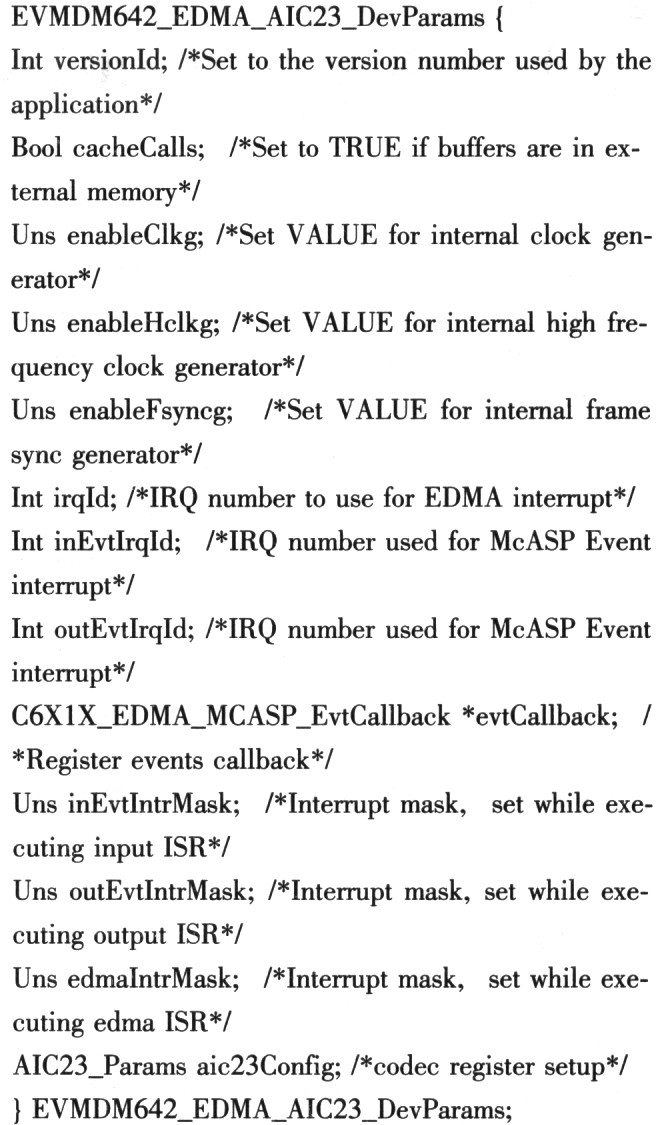
In general applications. Most of the parameters of the above structure do not need to be changed. The main thing that needs to be modified is aie23Config. It is the TLV320AIC23 control register value. It is necessary to control the TLV320AIC23's working mode, input / output selection, and sampling rate.
In addition to the reset register. TLV320AIC23 has a total of 9 control registers. The control word length of each register is 9 bits. The address bit is 7 bits, a total of 16 bits. The address bit is the upper 7 bits and the control word is the lower 9 bits. details as follows:
Register0: Left channel input volume control, the default value is 0x0017
Register1: right channel input volume control, the default value is 0x0017
Register 2: Left channel output volume control. The default value is Ox01F9
Register 3: right channel output volume control, the default value is Ox01F9
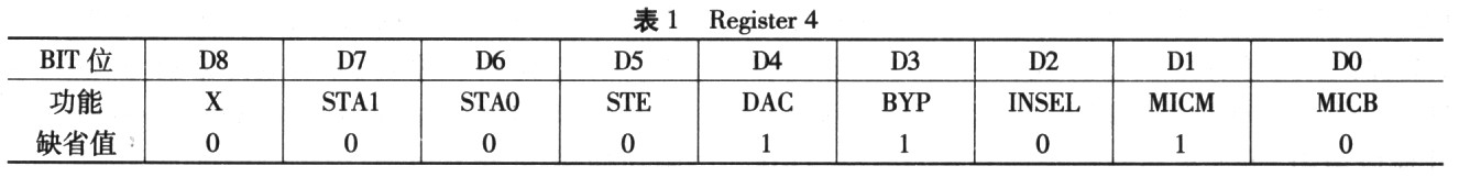
Register 4: Analog audio channel settings. The default value is Ox0011
Register 5: Digital audio channel settings. The default value is 0x0000
Register 6: Power saving mode control. The default value is 0x0000
Register 7: Digital audio interface format control, the default value is 0x0043
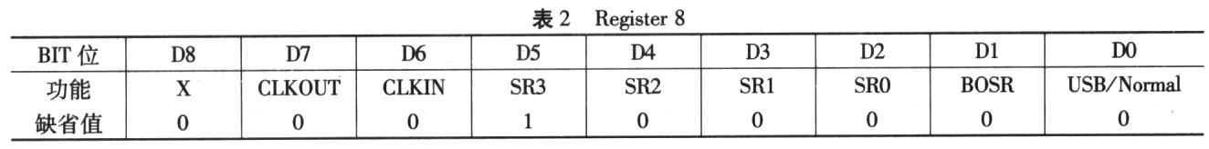
Register 8: Sampling rate control, the default is 48kHz, for DM642EVM board. The default value is Ox0002
Register 9: Digital audio interface activation switch. The default value is 0x0001
Generally, the registers that need to be modified include No. 4 and No. 8 registers. That is, whether to select mic input or line in input and select the sampling rate as required. The detailed configuration of these 2 registers is as follows:
The configuration of No. 4 register is shown in Table 1, among them, D2 bit. INSEL (In-put select for ADC) is input selection, "O" is line in; "l" is mic. D1-bit MICM (Microphone mute) is mic mute switch. "L" means mute. If the DO bit MICB (Microphone boost) is set to "1", it will provide 20dB of gain for the mic input. The configuration of No. 8 register is shown in Table 2. Among them, the sampling rate control bits are SR [3: O] of D5 ~ D2. For the DM642 EVM board, see Table 3 for the setting method.
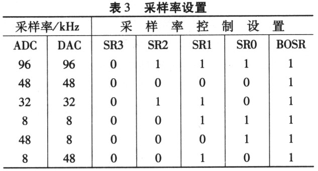
It can be seen that the input needs to be selected through D2 of No. 4 register, and the control of Dl and DO for mic is considered at the same time; the control of the sampling rate is achieved by setting SR [3: 0] of No. 8 register.
3 TLV320AIC23 drive configuration method
When many beginners run the DM642 EVM echo or other audio routines, the most likely problem is that there is output when input through line in. There is no output when input through mic, let alone changing the sampling rate. Even if the reference materials edit aic23-h and emvdm642_edma_aic23.h and modify Dcfauh parameters, it still cannot be solved.
When such a problem occurs. First, we must understand that the analog audio input of TLV320AIC23 is one of mic and line in. Second, we must know how to correctly configure the parameters of TLV320AIC23 to meet the needs of specific applications. If you carefully analyze the echo routine and other audio routines, you can find that only the echo routine contains aie23.h and emvdm642_edma_aie23.h 2 header files. In fact, in the echo routine. The two header files and the initialization statement of TLV320AIC23 are not actually used. If you block the inclusion of these two header files and the initialization statement of TLV320AIC23, you will find that it still runs normally after compilation. In fact, the TLV320AIC23 initialization statement in the echo routine only provides a way to configure II, V320AIC23 and is not used directly. This method has also been mentioned in the description file of the emvdm642 part of the DDK package.
Because the initialization driver population in the echo routine uses the same default parameters as other audio routines, and the default parameters are obtained by calling the evmdm642_edma_aic23.164 library in the DDK package. If the library is unchanged, the configuration is also unchanged, so The above problems will occur.
After clarifying the above principles, it has been proved through practice that the following three configuration methods provided in this article can be adapted to various applications.
method one
Since the default parameters are obtained by calling the evmdm642_edlna_a-ic23.164 library, then naturally the purpose of modifying parameters can be achieved by modifying the library. The DDK package provided by TI contains the source code of various libraries. This makes it possible to modify the library files. The library generation project used in this article is evmdm642_edma_mc23_64.pjt in the tiddksrc \ audio \ evmdm642 directory. You only need to open the project. Modify the default parameters in aic23.h and recompile to generate new library files. In this way, all audio routines will run according to the modified parameters by default.
This method is suitable for applications where the TLV320AIC23 parameter configuration is relatively fixed. Configuration is done by calling the evmdm642_ed_ma_aic23.164 library during initialization. No additional code needs to be added to the application project file. The project file is more concise. The portability is higher.
Method Two
Customize the structure conforming to the standard structure EVMDM642_EDMA_A.IC23-DevParams, for example:
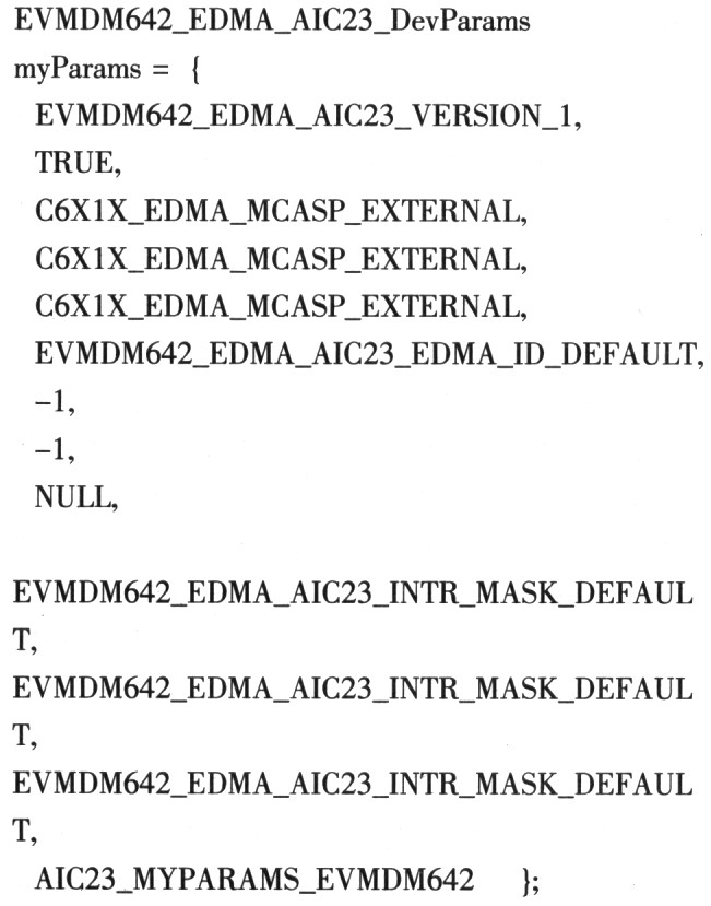
Then use "_myParms" as Device params ptr to replace the default 0x0 when specifying the population pointer. This conforms to the method recommended by TI, and the relevant code in the echo routine also illustrates this method.
This method can adapt to almost any use case, the initialization parameters are very clear, and the code is easy to read. However, it is not recommended to directly include a header file with default parameters as in the echo routine. It is best to refer to the header file to define your own structure.
Method three
Through careful analysis and generation of the source code of the evmdm642_edma_aic23.164 library, it can be found that the setting of the TLV320AIC23 register is done through the AIC23_setParams () function. In most cases, as long as you modify the register value without having to modify other variables in the standard structure EVMDM642_EDMA_AIC23_DevParams structure. So you can call AIC23_setParams () function to complete the configuration of TLV320AIC23 parameters. In this way, only one register array conforming to the standard needs to be defined. The AIC23_setParamsf () function can be achieved by using the array name as a parameter.
This method is flexible to use, the code length is very short, the meaning is very clear, it can be called multiple times with different parameters. It is especially suitable for special occasions with variable parameters of TLV320AIC23.
4 Conclusion
Based on the actual work, the author proposes three methods for TLV320AIC23 parameter configuration, each with its own characteristics and very practical. In the design of TLV320AIC23 driver program based on DDK, it can be conveniently selected according to the needs.
The Description of 3G Rubber Antenna:
The 3G Rubber Antenna is a multiband Covert Omni Antenna that allows the use of multiple frequency bands with a single antenna. Suitable for Frequencies: HSDPA, UMTS (3G) (1920-2770 MHz), GSM (2G) 900 (824-960 MHz), DCS 1800 (1710-1880 MHz)
3G Rubber Antenna Polarization: Vertical | 3G Rubber Antenna Connector Type: Customized | Impedance:50 ohm | VSWR:2 Input

The Advantage of 3G Rubber Antenna:
1,Rich experience , proven technique
2,Reasonable price
3,Wider frequency
4,OEM/ODM available
5,Perfession servie
6,ISO:9001 certification
7,1 year guarantee
8,Fast delivery time
9,R&D
10,Huge Capacity
3G Rubber Antenna
3G Rubber Antenna,Black Rubber Antenna,Folding Rubber Antenna,Omni 3G Antenna
Shenzhen Yetnorson Technology Co., Ltd. , http://www.yetnorson.com