Fixed frequency boost converters are ideal for driving LED strings in constant current mode. Operating in discontinuous conduction mode (DCM), this converter can be effectively used for fast dimming operations, providing superior transient response over competing devices operating in continuous conduction mode (CCM). When the LED is turned on, DCM operation provides fast transient performance and recharges the output capacitor, thus minimizing the analog dimming of the LED. In order to properly stabilize the DCM boost converter, there is a small signal model. However, the AC analysis of the boost converter that drives the LEDs is different from the AC analysis of a boost converter using a standard resistive load. Since series diodes require DC and AC load conditions, care must be taken when deriving the final transfer function.
This article (ie, Part 1) does not use the traditional small-signal model of the discontinuous conduction mode (DCM) boost converter, but instead uses a simplified method based on the output current expression of the converter under study. In Part 2 (actual considerations), we will delve into the application, verify the measurement accuracy, and compare it with theoretical derivation.
Boost converter for powering LED strings
Figure 1 shows a simplified circuit diagram of a constant frequency peak current mode boost converter that drives a string of LEDs. The output current is continuously monitored by the sense resistor Rsense. A corresponding output voltage is applied to the control circuit to continuously adjust the on-time of the power switch to provide a constant LED current Iout. This is the controlled output variable.
When illuminated, the LED string produces a voltage across the LED connection. This voltage depends on the threshold voltage VT0 associated with each LED technology and its dynamic impedance rd. Therefore, the total voltage drop across the LED string is the sum of the threshold voltages of the LEDs, VZ, while the dynamic impedance rLEDs represents the sum of the series dynamic impedances of the LEDs. Figure 2 shows the equivalent circuit used. You can characterize the LED string voltage drop and its total dynamic impedance yourself. For measurement purposes, the LED string current is biased to its nominal current IF1. Once the LED is thermally stable, the total voltage drop Vf1 across the LED string is measured. Change the current to a slightly lower value IF2 and measure the new voltage drop VF2. Based on these values, you can calculate the total dynamic impedance, namely: DCM boost converter to drive the LED string to simplify analysis.pdf
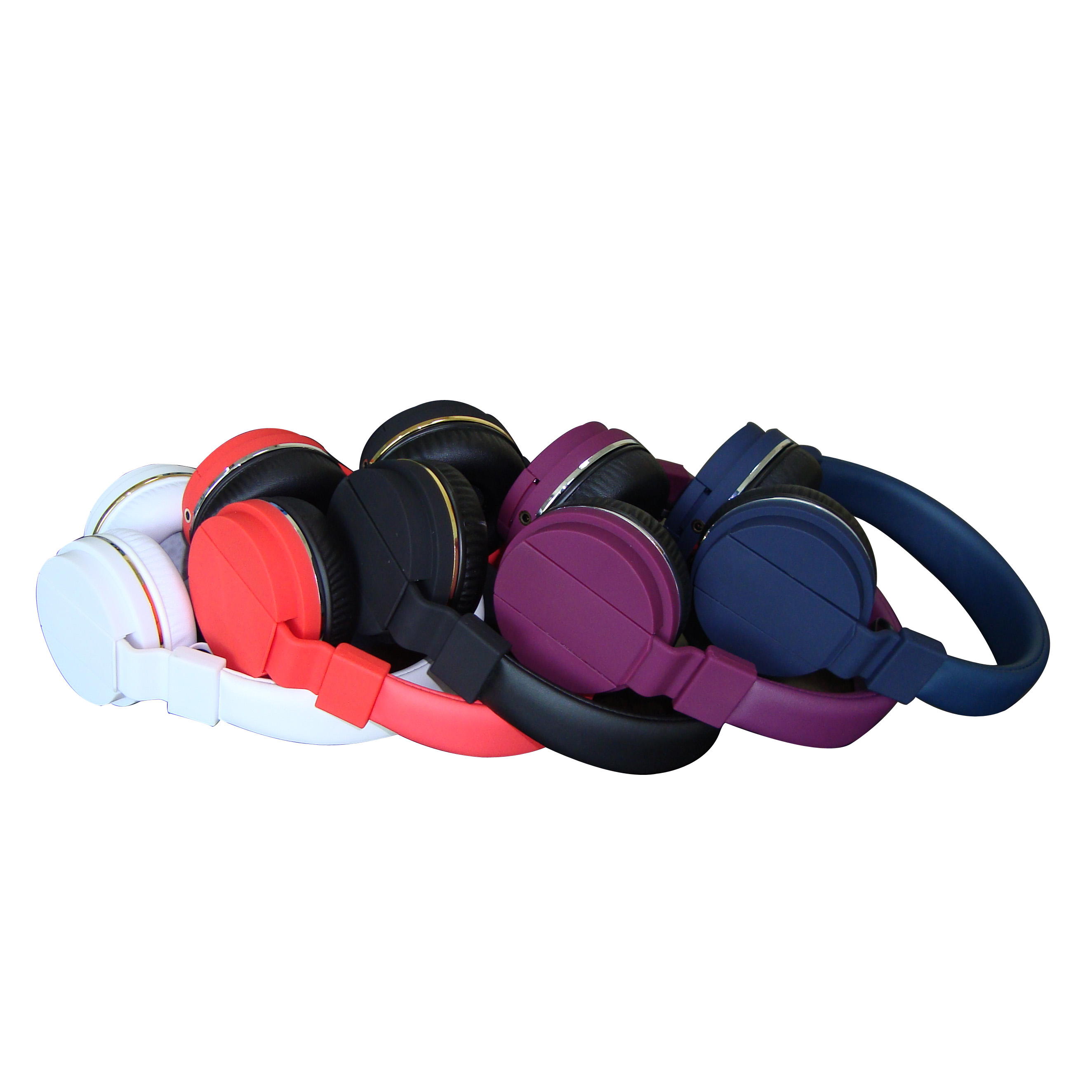
Studio Headphones/Audio Headphones/amazon headphones/Basic Wired Headphone
Studio headphone is suitable for many electronic equipment, such as mp3 Player, computer.
It\'s of high quality and fashion design. Pretty cool. Unique ear cups design is well matched with your ears.
1). Perfect voice, pretty cool appearance
2). Fashion colorful headphones design
3). Its frame is made from light, high rigidity material. Light and strong
4). CE and ROsH
5). Different color for choosing
6). Competitive price
7). Optimum impedance ensures universal compatability
8). Very comfortable, even if used for long periods of time

Studio Headphones,Beats Studio Wireless,Beats Studio 2.0 Wireless,Beats Studio Headphones
Shenzhen Greater Industry Co., Ltd. , https://www.szgreater.net