Abstract: In order to locate and track vehicles in dangerous goods transportation, passenger transportation, freight transportation, engineering vehicles and other special industries, GPS real-time monitoring system is realized by GPS positioning system and GPRS communication technology. GPRS communication technology is used as information transmission carrier in vehicle. The terminal, the monitoring center conducts data communication, GPS positioning and WebGIS technology to display vehicle information in real time; the system has fast communication speed, strong communication format scalability, high communication reliability, strong control of the client to the vehicle, and the front end uses Web page display Vehicle status and location, the system does not need to be installed, and the user is convenient to use.
Keywords: vehicle monitoring system; GPS; GPRS; UDP
0 Introduction With the development of China's economy, vehicles are increasing, transportation management, transportation and passenger transportation safety management have become an important issue in public security and transportation systems. The vehicle monitoring system is based on Global Positioning System (GPS) and GPRS (General Packet Radio service) communication technology. It can transmit real-time positioning data received on the vehicle unit to the monitoring center server through the wireless network for monitoring. The central computer reuses the map display function of the geographic information system and the transmission function of the signal command to realize the tracking and scheduling control of the dynamic vehicle, thereby establishing a large-scale, all-round function, real-time, accurate and efficient. Integrated vehicle scheduling and management system. Based on the Internet network, the system integrates the monitoring center, remote monitoring terminal, data server, wireless mobile communication network and GPS vehicle terminal organically, and realizes distributed monitoring with the Internet server as the core.
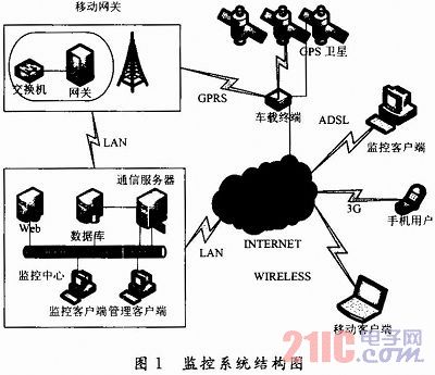
1 System structure The GPRS-based vehicle monitoring information system consists of four main components, namely the monitoring service center, the vehicle terminal, the monitoring terminal and the wireless communication network. The monitoring service center is the core part of the system, which connects the vehicle terminal and the client. The monitoring service center is composed of a web server, a communication server, and a database server. The communication server accepts the data of the in-vehicle terminal and forwards the data to the web server and the database server. The structure of the system is shown in Figure 1.
This article refers to the address: http://
2 system key technology
2.1 GPRS communication technology and UDP data transmission protocol Communication equipment is required between the vehicle and the monitoring center to transmit or receive information. The choice of communication means is the difficulty and technical key of the monitoring system. The choice of reasonable communication mode can provide a stable and fast platform for the command and dispatch and alarm processing of the monitoring system.
The vehicle monitoring system uses a GPRS network as a transmission carrier. GPRS is an efficient data transmission method using packet switching and transmission technology. It overcomes the shortcomings of low circuit switching rate and poor resource utilization, maximizes the utilization of existing GSM network resources, and improves the transmission rate. Compared with the short message method, the GPRS service not only improves the quality but also reduces the usage cost. The communication between the mobile vehicle terminal and the monitoring and dispatching center is strong, and each time the data volume is small, it is an ideal solution to use the GPRS network as its transmission carrier. The GPRS communication is mainly divided into TCP and UDP protocols.
The CP and UDP protocols are in the same transmission layer. Because the amount of data transmitted by the system is small and bursty, the UDP protocol is used to transmit data. The main function of the UDP protocol is to compress the network data stream into the form of datagrams. A typical datagram is a unit of transmission of binary data. The UDP protocol is an unreliable transport protocol and does not provide a guarantee mechanism for data transmission. If there is a loss of datagrams during the delivery from the sender to the receiver, the protocol itself cannot make any detections or prompts. Therefore, an acknowledgment mechanism for ensuring the reliability of information transmission must be added to the protocol of the application layer. When the monitoring center transmits data to the terminal, the terminal is required to return to receive correct or incorrect confirmation information. After the monitoring center receives the correct confirmation information, the data downlink process is completed. Otherwise, the monitoring center will resend within the specified time until it receives the correct confirmation message or the number of times the message overflows.
GPRS network UDP port resources are very scarce, change very fast; UDP due to its own characteristics, and the limited nature of GPRS network UDP port resources, after a period of time without data traffic, the port is easy to change, the impact is from the server center to the GPRS terminal The data is sent and the GPRS terminal does not receive it. The reason is that the mobile gateway has made a transit from it. It needs to send a UDP packet to the host to maintain the IP and port number, so that the host can send UDP packets to GPRS. The author found that the interval is very short. After 1 minute, the UDP packet can be maintained. If the mobile gateway is used for a long time, the port will be lost. The overdue host wants to send data to the terminal and will not be able to deliver it. Only when the GPRS terminal device resends a UDP packet, the mobile then allocates a transit IP and port to enable two-way communication. To ensure port validity and data real-time performance, the terminal device sends a data containing the location and status to the server every 5 s.
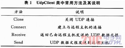
2.2 The main method used by C# to send and receive UDP packets (1) UDP data class. Using Visual C# to implement UDP protocol, the most commonly used and most critical class is UdpClient, which is located in the namespace System. Net. In Sock ets, Visual C# sends and receives UDP packets through the UdpClient class. The UdpClient class mainly has the following methods, as shown in Table 1.
(2) Accept terminal UDP data. The UDP packet is received using the "Receive" method in UdpClient. The calling syntax of this method is as follows: public byte[]Receive(ref IPEndPoint remoteEP); The parameter remoteEP is an instance of the IPEndPoint class, which represents the node in the network that sends this packet. The following is to get the information code by listening to the local port number "8 080":
UdpClient server=new UdpClient(8080);
IPEndPoint receivePoint=new IPEndPoint(IPAddress.Any,0);
Byte[]recData=server. Receive(ref receivePoint);
The recData is the received UDP packet. The UDP header structure is as follows: the source port is 16 bits, the destination port is 16 bits, the length is 16 bits, and the checksum is 16 bits. As explained above, the GPRS UDP port is very scarce and will change at any time. After receiving a UDP packet, you must record the source port and IP address. The receivePoint parameter is a reference type. After receiving a new UDP, the address and port attribute values ​​of the receivePoint object are the IP address and port of the sending source. This IP and port is not necessarily the IP and port of the real terminal. Because the application on the terminal binds a local port (for example, 9002), the request is sent to the router through this port, and the router records the intranet IP and port (9002) of the terminal, and then the router assigns one of its own free ports ( For example, 7000), send a request to the monitoring center through this port (7000). For the monitoring center, it does not have any information about the terminal, all it has to do is return the information to the router's external network IP port 7000. After the router receives the data sent to its 7000 port, it will forward it to the terminal.
(3) Send a UDP datagram. Send a UDP datagram using the "Send" method. The calling syntax of the "Send" method is as follows: public int Send(byte[]dgram, int bytes, IPEndPoint endPoint); Parameter description: UDP datagram to be sent by dgram (in bytes array). The number of bytes in the bytes data report. endPoint is an IPEndPoint that represents the host and port to which the datagram is to be sent. The return value is the number of bytes sent. The following is a specific call example for sending a UDP packet using UDPClient: 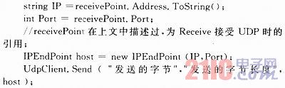
This code implements a reply to a terminal after sending a UDP packet. If you need to send a message to the terminal actively, you need to extract the last IP and port number of the terminal from the database, and call this method to send the content.
2.3 Data Encapsulation and Deduplication There are two types of data communication between the monitoring center and the client: one is uplink data and the other is downlink data. The uplink data includes status information of the terminal reporting vehicle, vehicle real-time information, vehicle voice information, video information, and the like. The downlink information includes information such as responses to the terminal, real-time control of the vehicle, and the like. There are more than one hundred kinds of data, which can be divided into more than 20 formats. A structure is defined for each format for data acceptance and dumping to the database for data display and analysis. The data returned by the terminal is generally a structure type. To ensure accurate and convenient data conversion, C# also uses the same structure to accept data. The text received by the UDP packet is a byte type, and the byte content includes a packet header and a packet type, a check portion, and a body. Find the corresponding C# structure structType according to the message type. Use Marshal. SizeOf(structType); Get the structure size and allocate space: IntPtrstructPtr=Marsh al. AllocHGlobal(size); Then copy the byte array to the allocated memory space: Marshal. Copy(recData,0,structPtr,size); converts the memory space to the target structure objectobj=Marshal. PtrToStructure(structPtr. struct Type). In order to improve the real-time response speed of the system, the data is divided into two processing methods, such as non-emergency data directly saved to the database, and if it is urgent data, such as vehicle alarm data, the vehicle control data is directly sent to the web server through the Socket connection. Pushed by the web server to the browser monitor.
3 Conclusion This paper mainly analyzes the GPRS communication technology of the monitoring system, and introduces the UDP data communication process and method based on GPRS in detail, and realizes the key technologies of accepting, sending UDP data messages, protocol customization, data transfer and other technologies in C# environment. The problem solved in this paper is the core content of the monitoring system, but not all. A complete system should also include terminal hardware design, background monitoring software, GIS map display and many other aspects. In the future, further research should be passed. Solve other related technologies of the system.
Zener Diode, the English name Zener diode, also known as Zener diode. By using the reverse breakdown state of the pn junction, the current can be varied over a wide range and the voltage is substantially constant, and the diode that acts as a voltage regulator is fabricated. [1] This diode is a semiconductor device that has a very high resistance until the critical reverse breakdown voltage. At this critical breakdown point, the reverse resistance is reduced to a small value in this low resistance region. The current is increased and the voltage is kept constant. The Zener diode is binned according to the breakdown voltage. Because of this characteristic, the Zener diode is mainly used as a voltage regulator or voltage reference component. Zener diodes can be connected in series for use at higher voltages, resulting in higher regulated voltages in series.
Zener Diode
Power Zener Diode,Zener Diode,Zener Diode Regulator,Zener Diode 56V
Dongguan Agertech Technology Co., Ltd. , https://www.agertechcomponents.com