Since the 1950s, with the development of microelectronics technology, communication technology and computer network technology and the wide application of large-scale integrated circuits, the digital circuit fault repair of electronic equipment has become more and more complicated, and the test difficulty has become more and more serious. At the same time, digital circuit test and diagnostic research has also made breakthroughs, which are pseudo-exhaustive methods, Boolean difference method, feature analysis method, random test method, D frontier sensitization method and causality of combined circuit test generation algorithm. The function method, which belongs to the time frame expansion method of the sequential circuit test generation algorithm and the simulation-based method, makes the diagnosis theory of the digital system tend to be perfect. However, the calculation of digital circuit fault diagnosis is complicated, and the test cost is huge. There are still many difficulties in engineering practice. Therefore, how to use these theories and test methods to diagnose faults better and faster is an urgent problem to be solved. The development of automatic test equipment (ATE) is a revolution in test technology, bringing the maturity of test equipment and providing new prospects for engineering applications in test diagnostic theory.
This article refers to the address: http://
Aerospace Measurement and Control Company is aiming at the development requirements of digital circuit automatic test system. The more complex sequential circuit test in digital circuit is the focus. The digital circuit including CPU and FPGA is used as the test object, and it is successfully developed in combination with the commonly used sequential circuit simulation method. A portable automatic test system based on PXI bus technology (HTEDS8300 portable PXI bus digital circuit board test diagnostic system). The system is characterized by high cost performance, small size, easy to carry, and difficult to develop TPS. It is suitable for design verification, testing and maintenance of semiconductor, aerospace/defense, and communication consumer electronic products in military and civilian fields. The hardware and software components and characteristics of the HTEDS8300 portable PXI bus digital circuit board test and diagnosis system are described in detail below, and the system is used to implement automatic test of the digital circuit board containing the CPU.
PXI (PCI Extensions for Instrumentation) is a PC-based modular instrumentation platform for measurement and automation systems. It combines the electrical performance of the PCI bus with CompactPCI's rugged, modular, and EK mechanical features, and adds hardware features such as trigger bus and local bus for instrumentation, making it a measurement and automation system. A high performance, low cost development platform. HTEDS8300 portable PXI bus digital circuit board test and diagnosis system uses PXI chassis embedded controller, the structure is light and compact, easy to carry.
The system adopts the function test method, directly uses the input and output interfaces of the circuit as the excitation point and the response point, and compares with the expected response to determine whether the tested board is working normally and locates the fault to the minimum replaceable unit. For internal nodes in the board, they can be connected by fixtures, probes, etc.
The system is equipped with four digital I/O modules for digital signal transmission and acquisition. Considering that a typical CPU board contains at least 32-bit address lines and 32-bit data lines and other control lines, the system is equipped with 104 digital I/O channels with a maximum data rate of 50 MHz and a maximum of 352 channels. When testing digital boards with CPU and FPGA, the test port needs to change direction according to the timing. The test system has real-time dynamic input and output direction test capability, and can perform real-time hardware comparison on the collected response data.
At present, most of the digital circuit boards have chips with boundary scan ports. In order to meet the test requirements of such boards, the system provides a boundary scan test channel conforming to IEEE1149.1.
In addition, the digital oscilloscope module is configured in the system. This is mainly because in the digital circuit test, especially in the high-speed digital circuit test, the oscilloscope is needed to observe the dynamic waveform and measure the rise/fall time of the waveform, so as to Provide a basis for troubleshooting. The test system is also equipped with a 6.5-digit digital multimeter that measures voltage, current, resistance, inductance, capacitance and impedance. In this way, different resources such as digital I/O and oscilloscope can work synchronously during the test, and the automatic test method is more flexible and can meet the user's testing requirements for complex digital circuits.
The system is equipped with an external board test fixture that can be rotated 180 degrees freely, allowing testers to pin the board while analyzing and testing the board, and flip the board to measure both sides of the board.
The system is suitable for testing and diagnosis of various types of digital circuit boards, and isolates faults to the smallest replaceable unit (component) that fails. The test scope includes: medium and small scale integrated digital circuit PCB; medium and small scale Programmable logic series chip; PCB with large scale integrated circuit with boundary scan interface, CPU chip, DSP signal processing circuit, and other kinds of digital circuit PCB.
The system software is mainly composed of test diagnostic program (TPS) development, test diagnostic program execution, comprehensive query, information sharing, system maintenance, system security, and online help. It can realize the development and execution of test diagnostic programs for various types of PCBs. The system obtains the information obtained through the test and analyzes and judges the test diagnostic program to complete the fault detection and positioning of the PCB.
In order to make the board test and maintenance personnel break the tradition of completing the board test diagnosis by writing the code program, the technical difficulty of the developer editing the TPS is reduced. The software platform adopts the graphical TPS editing environment to provide a general development environment and can complete different types. The development, debugging and operation of the circuit TPS, the system software can use the standard IEEE1445 format data output by the digital circuit simulation software to test the circuit board, which improves the work efficiency and development quality of the TPS developers.
The software platform provides a visual interface wizard function, and utilizes various process modules provided by the platform to cooperate with corresponding functional components. The user only needs to input expert knowledge and other necessary information to establish a specific diagnostic program. Developers do not need to learn and perform complex source code coding to complete TPS development, avoiding the drawbacks of a previous circuit module corresponding to a set of diagnostic software, with strong versatility and scalability.
At present, most digital circuit board test systems are basically for testing and troubleshooting digital boards without CPU and FPGA. The commonality of such boards is the one-to-one correspondence between response and excitation, that is, automatic control by the program. The test device inputs a signal to the board. When the input of the board is determined, the board generates a corresponding output signal. According to the fixed input-output relationship, it is easy to judge the fault of the board and judge the faulty node. However, for boards with microprocessor components, this test method cannot be simply used to perform fault detection on ATE devices. Since the microprocessor uses a three-bus or programming port to control the circuit, the timing of the input and output of such a board is not fixed, and the input and output responses are not necessarily one-to-one. In response to this problem, the bus signal or the port signal must be reliably controlled to determine the fault to ensure that each time the synchronous test is performed, that is, each time the input excitation signal is consistent in timing. When this is compared with the expected response signal, the fault will not be misjudged due to the timing difference.
The control signal of the microprocessor is actually a digital signal, and the test system can provide more than 104 dynamic I/O signals. Therefore, the I/O signals of the test system can be used to simulate the signals of the microprocessor pins, and the driving circuit Other functional modules, so as to achieve analog microprocessor component timing, complete the purpose of synchronous testing, and effectively detect the failure of other functional modules. If the other functional modules are normal and the board is not working, the fault can be located on the microprocessor.
Take a CPU equipment board as an example to verify the I/O test capability of the system. The board CPU controls the FLASH, the temperature sensor, and the drive motor through a serial-parallel bus.
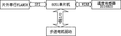
Circuit block diagram
The platform can select the I/O signal level voltage, change the I/O signal direction every cycle, edit the test excitation and response signals in the graphical development environment provided by the software, and collect the response signals to test the board interactively. . The system can accurately locate circuit board faults and effectively improve test efficiency.
Gaming Headset /Gaming Headset With Microphone /Stereo Gaming Headset /USB Gaming Headphones
Features:
1. Popular gaming headset with custom logo with different color
2. Manufacture with competitive price & good quality
3. Excellent sound performance
4. Material:PVC
5. Custom packing design service
6.Use for Fashion Show and Internet bar

Gaming Headset
Gaming Headset,Amazing Gaming Headsets,Gaming Headset Ps4,Gaming Headset Usb
Shenzhen Greater Industry Co., Ltd. , https://www.szgreater.net