1 Traditional digital PID algorithm
1.1 Position control algorithm
The positional PID control algorithm is described as:
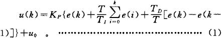
make
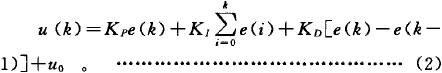
In the formula: k——Sampling serial number;
u (k) —— The calculation result of the kth sampling time;
e (k) —— The deviation value of the first sampling relative to the target position;
Kl——integration coefficient;
KD-differential coefficient;
KP——Proportional coefficient;
TI——integration time constant;
TD-differential time constant;
T-sampling period.
It can be seen from equation (2) that each output is related to the past state. To calculate u (k), not only involves e (k-1), but also must add the previous times. Therefore, the formula (2) is complicated and wastes memory. When the control is switched from manual to automatic, the output value of the computer must be set to the original valve opening uD in order to ensure no impact switching.
1.2 Incremental control algorithm
The incremental PID control algorithm is described as:
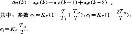
The incremental type only needs to calculate the increment. When there is a calculation error or insufficient accuracy, it has little effect on the calculation of the control quantity. Since uO does not appear in the calculation, it is easy to realize manual to automatic switchover without impact. In addition, when the computer malfunctions, the execution device itself has a registration function, so it can still remain in place.
Based on the above two conventional algorithms, we have proposed a variety of improved algorithms in practical applications. In this project, the integral separation PID control algorithm is used.
2 Integral separation PID algorithm
The mathematical model of the integral separation control algorithm is as follows:
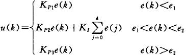
Among them, e1 and e2 respectively represent the left and right intervals, that is, the distance from the target position, which is a conventional integral separation PID control algorithm. In actual application, it can be segmented again according to different systems and actual conditions. 3 Algorithm in position servo system
In the system we studied, the method used was multiple integral separation and integral separation in the process of forward and reverse overshoot.
First of all, we describe the mathematical model of the parameter tuning used, and the segmentation is shown in Figure 1.

Figure 1 Segmented circle
In Fig. 1, 1 and 7 indicate that there are positive and negative points in the full-speed exercise section. Right is positive and left is negative; 2 and 6 indicate the interval of using pure proportional adjustment control at the left and right of the target position; 3 and 5 indicate the parts that need to use the conventional PID algorithm; 4 indicates use within a small error range Proportional integral control.
The above segmentation is a segmentation for the actual system and is a segmentation method suitable for this system. It not only meets the requirements in terms of speed and accuracy, but also is more suitable for this system than other methods we have used.
4 Parameter tuning
Since the system we are studying is a system with high position accuracy requirements, the parameter setting requirements are relatively high. On the basis of continuous experimentation, a set of methods suitable for this system to obtain parameters by approximate calculation is summarized.
Since this system is a servo system, it is difficult to establish an accurate mathematical model of the system. We only know that the magnification of the forward channel is N, the motor saturation voltage is U1, and the maximum speed of the motor is v1. The setting of the position loop parameters affects the accuracy and rapidity of the entire system. Based on continuous experiments, we summarize the following methods:
(1) Segment the system accordingly. Segmentation is determined based on experiments. Since the system itself is a complex, non-linear, high-order system, segmentation is a relatively important link. Through experiments, the step response of the system under different conditions is continuously tested and used as a segment. in accordance with.
(2) Determine the parameters of the last algorithm part. We use different PID algorithms for different locations, where the voltage at the turning point is a more critical parameter. According to the experiment, we determined that the voltage output by the algorithm multiplied by the magnification of the forward path as the voltage value loaded on the motor, Of course, this voltage value must make the motor still have speed under load.
(3) Determine the scale factor of the 2nd and 6th stages. The scale factor here is obtained by the voltage and displacement of the two turning points, which is a linear function relationship, that is, U output = KPS displacement. Among them, U output is the output part of the algorithm; KP is the proportional coefficient of 2 sections and 6 sections; S displacement is the displacement amount relative to the target position. Through the transition between 1 and 2 or 6 and 7, you can get a set of U output, S displacement, and through the transition between 2 and 3 or 5 and 6, you can get another set of U output, S displacement, thus Determine KP.
(4) Determine the PID parameters of paragraph 4. From the voltage value of the turning part obtained above, we have the starting voltage, and then according to the obtained starting voltage, the proportionality coefficient can be determined. When determining this scale factor, the integral and differential coefficients must be zero. Through the determination of this scale factor, we can get the required parameters completely through calculation. In order to meet the accuracy requirements, the parameters can be set by adding appropriate integral terms based on experience. Note that the smaller the integral term is, the better, of course, within the range of guaranteed accuracy.
5 Conclusion
Experiments show that the motion process we obtained meets the requirements of rapidity and precision. The plan summarized in the experiment is feasible and reasonable.
Twins Bluetooth Earphone are popular for its idea, function and beauty. Barrier-free transmission distance over 10 meters, connection is not stuck, and strong penetration. Answer/end/reject/transfer, call waiting, redial, mute, multi-purpose devices connection, music pause/play/next, noise reduction, stereo, etc. It should be the first choice of Bluetooth Earphone.
Twins Bluetooth Earphone
Twins Bluetooth Earphone,Twins Wireless Bluetooth Earphone,Twins Wireless Earbuds,Double Earphones
ShenDaDian(China) Digital Electronics Co.,Ltd , http://www.btearbuds.com