Direct drive motor (dd motor, dynaserv) is widely used in certain occasions because it does not require a reducer, which is equivalent to what we call a torque motor, but the former uses a new type of AC motor principle and is digitally controlled. of. The intelligent driver drvgâ…² of Yokogawa (yokogawa) is used as an example to introduce its filter. The drive is a newer model, which can more comprehensively summarize the usage of other models.
Oscillation type
There are mainly the following types of instability:
1) Adjust oscillation
Low-frequency oscillations with a frequency of a few hertz and oscillation amplitudes of a few degrees to tens of degrees, sometimes exceeding the control area. It is caused by the imbalance between the position control frequency bandwidth and the speed control frequency bandwidth. For example, the speed control frequency bandwidth is less than 3 times the position control frequency bandwidth. It can also be that the inertia moment value is not suitable during automatic adjustment, such as when it is greater than 1.5 times. You can repeatedly perform the automatic adjustment operation and check the inertia value, and the error cannot be greater than 20%. Or reduce # 0 parameter setting value (servo stiffness setting parameter).
2) Crawling
The vibration phenomenon is similar to the adjustment oscillation. When the low-speed running command is executed, the stop and go are repeated, which is caused by the static friction force being greater than the dynamic friction force at low speed. The reason is that the position integration limit value is too large, and the position deviation is too large, which makes the control system unstable. The method is to adjust the "integral limit" or increase the system stiffness.
3) Phase shift oscillation
The oscillation frequency is tens to 200hz, and the oscillation amplitude is not less than tens of degrees. The reason is that the phase of the speed output signal lags behind the phase of the speed input signal by 180 °, and it is known from the control theory that the system has no stable margin at this time. This oscillation can be caused when various filters use the same frequency or the speed control bandwidth and the filter frequency bandwidth are the same. The processing method is to reduce the parameter setting value of # 1 (servo stiffness setting parameter).
4) Resonance
The oscillation frequency is tens to 2khz, and the oscillation amplitude is at most several degrees, depending on the structure. Small amplitude and high frequency, tremor noise can often be heard, the system stiffness is easy to cause this phenomenon. The cause is that the mechanical resonance disturbance of the load enters the speed control loop, and there are several resonance frequencies in most cases. Therefore, when designing the system, the mechanical resonance frequency should be as high as possible, at least 5 times higher than the control bandwidth of the system, pay attention to the rigid design during the structural design, and avoid the slender rod structure. Adjustable filter suppression frequency resonance point gain to solve.
filter
There are three types of filters to eliminate oscillations. Choose according to the specific situation.
a. Phase lag compensation filter
It is a first-order delay filter. Because it can adjust the frequency of the bandwidth and increase the damping, it is better than the speed feedback filter in reducing the phase shift.
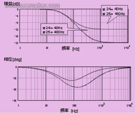
Figure 1 Bode diagram of phase lag compensation filter
Note that if the speed control bandwidth and the frequency setting of the first-order compensation filter are too close, it may cause oscillation.
b. Notch filter
Notch filter, also known as band stop filter, can effectively block any frequency signal, and even reduce the gain of the resonance point to zero. Applicable when the resonance peak is high and the frequency bandwidth is narrow. By changing the quality factor (q value), the attenuation characteristic changes sharply or gently. The frequency setting range is from 50 to 1500hz, and the q value setting range is from 0.5 to 2.5 (default value is 1.5). Figure 2 shows a notch filter setup diagram.
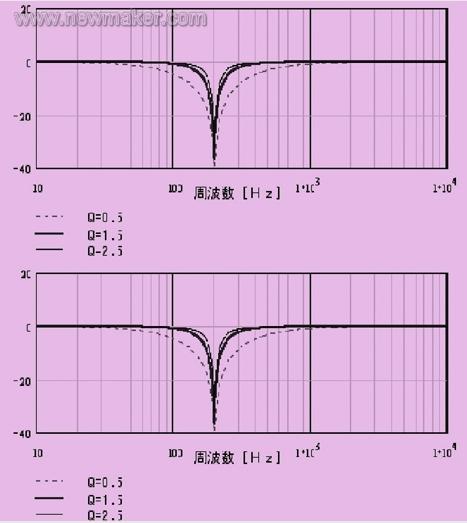
Figure 2 Notch filter settings
c. Speed ​​feedback filter
The velocity feedback filter is also a first-order delay filter, which is a pure inertial link and the phase shift tends to be 90 °. The gain is small at high frequencies and is applicable when there are several resonance points at high frequencies. The gain is specified as the bandwidth frequency at -3db, and the setting range is from 50 to 1000hz (see Figure 3). Note that the phase shift can reach 90 ° during use, and oscillation due to phase shift may occur.
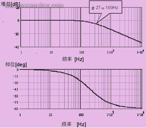
Figure 3 Bode diagram of speed feedback filter
1. First adjust notch filters 1 and 2 to minimize the oscillation value, and turn off the filter if there is no effect.
2. Adjust the phase lag compensation filter again.
# 24 = n × # 2
# 25 = 4 × # 24
Parameter # 24 is the first-order lag compensation frequency # 1;
Parameter # 25 is the first-order lag compensation frequency # 2;
Parameter # 2 is speed control bandwidth # 1.
Set parameter # 24 to try with n = 3, n = 2, n = 1. If the oscillation cannot be stopped, turn off the filter.
3. Decrease the value of parameter # 1 (servo rigidity setting). Return to step 1. Adjust repeatedly until you are satisfied.
If an error occurs during self-tuning, you can set the load inertia to zero and increase the auto-tuning range (parameter # 51, auto-tuning mode execution range). If it oscillates during self-adjustment, reduce the servo stiffness until the resonance stops. Repeat the self-adjustment and filter adjustment again.
Various types of such motors and drivers have their own software interface for debugging, controlling and setting parameters, either to the controller or to the driver, but they are similar, and will not be introduced here. During the debugging process, repeated experimental observations are required, and they are flexibly applied according to the requirements of use. For example, for a turntable test equipment composed of such motors, the requirements for speed stability during measurement are strict, but the acceleration is not strictly required, as long as the acceleration zone is not too long, there are many types of objects to be tested, such as weight, inertia, The stiffness varies and the test object is changed frequently. With automatic adjustment, resonance often occurs when loading, no-loading, or changing the load object. It is necessary to perform automatic adjustment again. For this reason, the author lowers the system gain, reduces the hardness of the output characteristics, sacrifices the speed and increases the stability, so that it does not oscillate or reduce the measurement accuracy under various loads. In another system, the author even disconnected the hardware of the band-notch filter and unplugged the connection plug to stabilize the system.
Drum type Rice Cooker
Features
This type rice cooker is famous with drum type appearance, which is easy operation and easy clean.
There are two type of inner pot , one type called white pot which is without non-stick but cheaper price .another one called non-stick pot is polished with emery, Also there are two type non-stick with different price ,it`s depending on different demands to use.
And the inner pot cannot be burned on the stove, which will make the pot transfigured and bad contact with the heating plate. While cooking , the heating plate or the fuse is most likely to be burned for the bad contact of the inner pot and the heating plate, Besides, make sure to dry the pot before putting into the outer shell of the rice cooker ,or else the drops of water flowing on the heating plate, will make the heating plate rusted.
Applications
Many peoples are used drum type rice cooker for congee and soup, some of peoples are prefer to use this type rice cooker for steaming.
Drum Rice Cooker,Drum Shape Rice Cooker,Electric Drum Rice Cooker,Multifunctional Drum Rice Cooker
Guangzhou Taipeng Electrical Appliances Technology CO., LTD. , https://www.taipengelectric.com