Distribution network automation is one of the important work contents of the national smart grid construction. Under the guiding principle of the national grid “unified planning, unified standards, unified constructionâ€, all kinds of companies participating in the distribution automation construction under the jurisdiction of the State Grid Corporation are When developing and producing distribution network terminal equipment (FTU/DTU), it is necessary to meet the application functions, performance indicators, system configurations and various types of terminal equipment in accordance with the State Grid Enterprise Standard Q/GDW382-2009 "Distribution Network Automation Terminal and Substation Specifications". Specification requirements for the interface.
Case description:
When designing and producing FTU system controllers, a manufacturer chooses an AC-DC power supply module with battery charging function to meet the requirements of FTU power supply from 220 VAC and backup power supply. The power module itself has met the relevant EMC performance level requirements, but the customer found that the system control board has abnormal operation such as reset and restart when performing the overall EMC common mode surge test project of the controller. According to customer feedback, in the design and selection, the isolated switch power supply products that meet the requirements of the EMC level have been selected in combination with the system parameters, and there should be no such abnormalities. This is easy to mistakenly think it is a power module problem.
To this end, according to the customer's design situation, combined with the relevant performance specifications, the overall power supply design analysis and rectification.
First, the cause analysis:
After communication, the parameter setting error and human error judgment are eliminated. When the customer performs the common mode surge level 4 test for the power supply circuit according to the standard specification requirements, the control board is abnormal when there is surge interference. At the end of the surge test The anomaly disappears synchronously. This indicates that the system board is indeed subject to common mode surge interference.
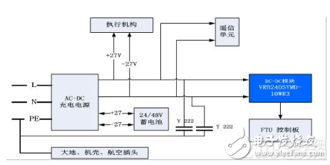
Figure 1 Customer FTU system power solution
Figure 1 above shows the customer's FTU system power solution. If we understand the EMC test operation specifications according to our routine, the power circuit surge is applied to the front-end AC-DC power module port. The common mode surge interference path exists on the closed loop path from L/N to PE. .
Path 1: AC-DC internal L/N directly to PE;
Path 2: connected to the PE through the L/N, AC-DC output, and Y capacitor;
Path 3: Space coupling to the PE through the L/N, AC-DC output, DC-DC module, and control board.
Since the control panel is affected, it must be affected by path 3. However, the voltage isolation of the AC-DC module is 3000 VAC and 1500 VDC, respectively, and the control board and the PE can only be spatially coupled, so the problem is obviously unable to directly determine the root cause.
Further communicate with the customer and found that the power circuit indicated by the standard actually includes two parts, input and output, which is different from the surge test of the power input of a single power module. The customer is an abnormal condition that occurs when the surge level four test is performed at the AC-DC power supply output.
Second, the test verification:
The surge test at the AC-DC power supply output according to the customer's voltage scheme is equivalent to the surge test at the DC-DC power input. Because the VRB-R3 series power bare metal does not have the corresponding surge resistance, and its various types of withstand voltage is only 1500VDC. Although it does not have a PE input, a common mode surge of 4KV will cause damage to the product, and its common mode interference will directly affect the control board at the back end; especially when the distance between the control board and the cabinet is very close, An interference path will be formed. The above interference analysis was also confirmed by actual simulation tests.
Third, the rectification process:
Combined with the three elements of interference (interference source, propagation path, and interfered object), the interference source is the common mode surge level 4 that meets the standard requirements. This factor cannot be eliminated and changed; the interfered object is that its control circuit cannot directly participate. Modification; therefore, optimization and rectification can only be done through the propagation path.
Optimization measure 1: Interference signal bypass processing on the propagation path
As shown in Figure 1, if the Y capacitor is directly replaced with a 20D470K varistor for clamping, and the back-end DC-DC has a certain isolation capability, the customer's overall experimental results are confirmed to be OK. However, such system standard specifications require that the output of the AC-DC meet the isolation withstand voltage of 2.5 KVAC for its PE terminal. The thermistor with low residual voltage cannot meet the withstand voltage requirement, so this optimization measure is not feasible. The customer needs to statically apply to the remote communication port. In order to ensure that the leakage current of the withstand voltage test does not exceed the standard, the Y capacitor needs to be retained.
Optimization measure 2: Signal suppression processing on the propagation path
As shown in Figure 2 below, adding FS-A01D is to suppress the interference interference on the replay path, and replace the DC-DC power supply module with the URF-R3 series with isolation voltage of 3000VDC to further improve the suppression capability of the interference signal; AC-DC output DC voltage positive and negative direct parallel 20D470 varistor, to avoid the impact of transient DC voltage fluctuations; and it is recommended that customers check the control board for external wiring and the housing is too close, need to use tape to avoid installation Close to the outer casing.
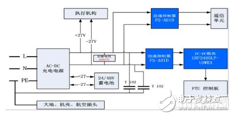
Figure 2 Optimized rectification of the FTU system power scheme
Fourth, summary:
1. Analysis method: Firstly, it is necessary to accurately locate the root cause of the problem - because the system standard and the specification requirements of the single power module are different, the surge test for the distribution network automation includes the AC-DC power output loop. After confirming the cause of the problem, theoretical guessing and experimental confirmation can be made for the problem.
2. Solution optimization: The old solution problem is that when the device specifications are initially selected, the standard differences are also neglected, so that the back-end DC-DC module has insufficient isolation suppression capability and no surge protection. When the new program is rectified, it is necessary to fully understand the relevant requirements of the customer's overall system, and avoid the problem of transferring surges into pressure resistance or static electricity.
The typical Electrical Wire harnesses that ETOP supplies include dozens of wires and sometimes hundreds of different components and terminations. Our engineering staff is well versed in the design and construction of wire harnesses and is available to assist in the development of the most efficient wiring harness to meet your demands. A basic Wire Harness may include as few as three discreet components, while the more classic harnesses include many more wires and other passive, and potentially active, components.
Electrical Wiring Harness, terminal wiring, wire assembling,bullet terminals, lead wire assembly
ETOP WIREHARNESS LIMITED , https://www.oemmoldedcables.com