When a call signal is input to a certain path, the signal is sent to the encoder (74LS148) for encoding. The encoder signal passes through the inverter (74LS04) and is output to the display circuit via the driver chip (CD4511) to display the path. coding. At the same time, the monostable circuit is triggered to generate a high level of 2s, so that the multivibrator works, so that the LED and the buzzer generate a 2S alarm signal, and the alarm state can be eliminated by a manual button. The circuit of the octal pager is mainly composed of an encoding/latching/decoding/display circuit, a monostable circuit, an alarm circuit/manual control circuit. Among them, CD4511 is a seven-segment digital tube driver chip with its own latch function.
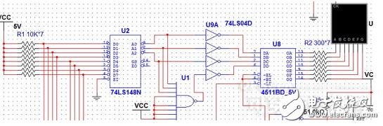
1. Encoding/latch/decode/display circuit
Circuit structure and working principle: The circuit consists of button, 8-3 line priority encoder 74LS148, inverter 74LS04, driver CD4511, seven-segment digital tube and protection resistor. When one of the buttons J1 to J8 is pressed, it indicates that there is a call on the road. There is a corresponding coded (inverse) output at the output of the 74LS148. The CD4511 is driven by the inverter input to drive the digital tube to display the corresponding number of buttons. For example, when the J3 button is pressed, it indicates that there is a call on the road where J3 is located, and the low-level input 74LS148 of J3 is encoded. After the inverter 74LS04 is inverted, input CD4511 decoding drive, the digital display shows the digital 2. The display circuit only needs to connect the CD4511 latch terminal EL to the monostable trigger output terminal, so that the display circuit can display the corresponding time (EL High level latch). Note: Because the 74LS148 can only encode 0-7, and the 74LS30 (8 and NAND) is connected to the CD4511 A4 pin via the inverter, the output “0†can be displayed on the digital tube with “8â€.
2 delay 2S alarm circuit
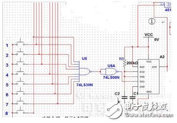
Circuit structure and working principle: The circuit consists of button, 8 NAND gate 74LS30, monostable circuit, NAND gate 74LS04, inverter, multivibrator, LED and buzzer. When one of the buttons J1 to J8 is pressed, it indicates that there is a call on the road. The 74LS30 outputs a high level, and generates a low-level trigger monostable circuit through the inverter, generating a 2S high-level delay, triggering the multi-vibrator 4 RST pin through two inversions to cause it to oscillate, thereby Controls LED and buzzer operation to generate an alarm. Among them, the manual elimination alarm circuit is composed of a latch 74LS374 and a NAND gate 74LS00, and the multi-vibrator 4 RST pin can be manually set low during 2S, thereby not working, that is, eliminating the alarm.
3 alarm circuit / manual control circuit
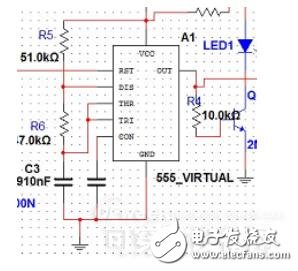
Circuit structure and working principle: The circuit consists of a button, a 2-input four-AND gate 74LS00, a six-inverter 74LS04, a triode, an LED light-emitting diode, and a protection resistor. Here the LED lights are extremely simulated brief alarm devices. When the button is pressed, the low level input is cleared by the inverter, and the LED light is off. Among them, J9, R17, VCC, and GND are equivalently replaced by 74LS374, which realizes the manual elimination alarm function during 2S.
Review analysis:
The main idea of ​​this design is to design a sound signal prompt when the patient makes an emergency call, and display the ward number, and then according to the patient's condition priority level. When multiple people call, the serious condition is preferred. For this circuit, be familiar with the 74LS148, 74LS374, CD4511, common cathode digital tube, 555, 74LS30 or 74LD686, 74LS00, 7805 and other integrated chip function table and related parameters and pin diagrams, while mastering the rectification of the regulated power supply, Filtering, voltage regulation working principle and understanding of circuit design, and finally flexible use of MulTIsim simulation software to detect module functions.
remote control car motor,rc boat engine,rc helicopter motor,slot car motors,toy motor price,toy dc motor
Shenzhen Maintex Intelligent Control Co., Ltd. , https://www.maintexmotor.com