Pick   To: zero intermediate frequency (Zero IF) or direct conversion (Direct-Conversion) receiver having a small size, low cost and ease monolithic characteristics, the structure is becoming a very competitive radio receiver. Local oscillator leakage (LO Leakage) Based on the Zero-IF configuration and structural performance characteristics introduced superheterodyne (Super Heterodyne), the focus of the present analysis of the zero-IF structure, even-order distortion (Even-Order DistorTIon), DC offset ( DC Offset) , Flicker Noise, etc., and the design method and related technology of the zero-IF receiver.
introduction
In recent years, with the rapid development of wireless communication technology, wireless communication system products have become more and more popular, and have become an important part of the development of human information society. The RF receiver is located at the forefront of the wireless communication system, and its structure and performance directly affect the entire communication system. Optimizing the design structure and selecting the right manufacturing process to improve the system's performance and price ratio is the direction that RF engineers are pursuing. Since the zero-IF receiver has the characteristics of small size, low cost and easy monolithic integration, it has become a highly competitive structure in RF receivers and has received extensive attention in the field of wireless communications. Based on the introduction of the performance and characteristics of superheterodyne structure and zero-IF architecture, this paper analyzes the possible problems of zero-IF architecture and gives the design method and related technology of zero-IF receiver.
Superheterodyne receiver
The Super Heterodyne architecture has been widely adopted since it was invented by Armstrong in 1917 . Figure 1 is a block diagram of the structure of a superheterodyne receiver. In this structure, the RF signal received by the antenna passes through a radio frequency band pass filter (RF BPF) , a low noise amplifier (LNA), and an image interference suppression filter (IR Filter) , and then performs the first down conversion to generate a fixed signal . Frequency intermediate frequency (IF) signal. Then, the intermediate frequency signal is removed by the intermediate frequency band pass filter (IF BPF) , and then the second down conversion is performed to obtain the desired baseband signal. The RF bandpass filter in front of the low noise amplifier (LNA) attenuates out-of-band signals and image interference. The image rejection filter before the first down conversion is used to suppress image interference and attenuate it to an acceptable level. Using the adjustable local oscillator (LO1) , the entire spectrum is downconverted to a fixed intermediate frequency. The down-converted mid-band pass filter is used to select the channel, called the channel selection filter. This filter plays a very important role in determining the selectivity and sensitivity of the receiver. The second downconversion is orthogonal to produce two in-phase (I) and quadrature (Q) baseband signals.
The superheterodyne architecture is considered to be the most reliable receiver topology because excellent selectivity and sensitivity can be obtained by proper selection of the IF and filter. Due to multiple frequency conversion stages, DC offset and LO leakage problems do not affect receiver performance. However, both the image interference suppression filter and the channel selection filter are high- Q band-pass filters, which can only be implemented off-chip, thereby increasing the cost and size of the receiver. At present, it is very difficult to integrate the two filters together with other RF circuits on one chip by using an integrated circuit manufacturing process. Therefore, the monolithic integration of the superheterodyne receiver is difficult to implement due to limitations in process technology.
Zero intermediate frequency receiver
Since the zero-IF receiver does not require an off-chip high- Q bandpass filter, monolithic integration can be achieved and is widely recognized. Figure 2 is a block diagram of the structure of a zero IF receiver. Its structure is much simpler than that of a superheterodyne receiver. The received RF signal is amplified by a filter and a low noise amplifier, and mixed with two mutually orthogonal local oscillator signals to generate two in-phase and quadrature baseband signals, respectively. Since the local oscillator signal frequency is the same as the RF signal frequency, the baseband signal is directly generated after mixing, and the channel selection and gain adjustment are performed on the baseband, which is performed by a low-pass filter and a variable gain amplifier on the chip.
The most attractive feature of the zero-IF receiver is that the intermediate frequency is not required in the down-conversion process, and the image frequency is the RF signal itself. There is no image frequency interference. The image rejection filter and the IF filter in the original super-heterodyne structure are both Can be omitted. In this way, the external components are eliminated, which facilitates the monolithic integration of the system and reduces the cost. On the other hand, the number of circuit modules and external nodes required by the system is reduced, which reduces the power consumption required by the receiver and reduces the chance of external interference of the RF signal.
However, the zero-IF structure has problems such as DC offset, LO leakage, and flicker noise. Therefore, effectively solving these problems is a prerequisite for ensuring the correct implementation of the zero-IF structure.
LO leakage (LO Leakage)
The local oscillator frequency of the zero-IF structure is the same as the signal frequency. If the isolation between the local oscillator port and the RF port of the mixer is not good, the local oscillator signal can be easily output from the RF port of the mixer, and then pass the low noise. The amplifier leaks into the antenna and radiates into the space to form interference to the adjacent channel. Figure 3 shows the leakage of the local oscillator. The local oscillator leakage is not easy to occur in a superheterodyne receiver because the local oscillator frequency and the signal frequency differ greatly, and the local oscillator frequency generally falls outside the frequency band of the pre-filter.
Even-order distortion (Even-Order DistorTIon)
A typical RF receiver is only sensitive to the effects of odd intermodulation. In the zero-IF architecture, even intermodulation distortion can also cause problems for the receiver. As shown in Fig. 4 , assuming that there are two strong interfering signals in the vicinity of the desired channel, the LNA has even distortion, and its characteristic is y(t)=a1x(t)+a2x2(t) . If x(t)=A1cosw1t+A2cosw2t , then y(t) contains the a2A1A2cos(w1-w2)t term, which indicates that two high frequency interferences will produce a low frequency interference signal through the LNA with even distortion . If the mixer is ideal, this signal will be shifted to the high frequency after mixing with the local oscillator signal coswLOt , which has no effect on the receiver. However, the actual mixer is not ideal. The isolation between the RF port and the IF port is limited. The interference signal will be directly connected to the IF port from the RF port of the mixer, causing interference to the baseband signal.
Another manifestation of even-order distortion is that after the second harmonic of the RF signal is mixed with the second harmonic of the local oscillator output, it is down-converted to the baseband and overlaps with the baseband signal, causing interference. 5 is shown.
Here we only consider the even distortion of the LNA . In practice, the mixer RF port will encounter the same problem and should be given enough attention. Because the signal applied to the RF port of the mixer is the RF signal amplified by the LNA , the port is the strongest signal amplitude in the RF path, so the even nonlinearity of the mixer will cause severe distortion at the output. .
The solution to even distortion is to use a fully differential structure in the low noise amplifier and mixer to cancel the even distortion.
DC offset (DC Offset)
DC offset is a type of interference unique to the zero-IF scheme, which is caused by Self-Mixing . The leaked local oscillator signal can be reflected back from the output of the low noise amplifier, the output end of the filter, and the antenna end, or the leaked signal is received by the antenna and enters the RF port of the mixer. It mixes with the local oscillator signal entering the local oscillator port, and the beat frequency is zero, which is DC, as shown in Figure 6(a) . Similarly, the strong interference signal entering the low noise amplifier will also leak into the local oscillator port due to the poor isolation performance of each port of the mixer. In turn, the strong interference with the RF port is mixed, and the difference frequency is DC. 6(b) .
These DC signals will be superimposed on the baseband signal and interfere with the baseband signal, known as DC offset. The DC offset is often larger than the noise at the RF front end, which makes the signal-to-noise ratio worse. At the same time, large DC offsets may saturate the amplifiers after the mixer and cannot amplify the useful signal.
After the above analysis, we can estimate the DC deviation caused by the self-mixing. Assume that in Figure 6(a) , the total gain from the antenna to point X is about 100 dB , the peak-to-peak value of the local oscillator signal is 0.63 V ( 0 dBm in 50 Ω ) , and the signal is attenuated when coupled to point A. a 60 dB. If the total gain of the low noise amplifier and mixer is 30 dB , the mixer output will produce a DC offset of approximately 7 mV . The signal level is useful at this point may be as small as 30 μ Vrms. Therefore, if the DC offset is directly amplified by the remaining 70 dB gain, the amplifier will go into saturation and lose the amplification of the wanted signal.
The DC offset problem becomes very complicated when the self-mixing changes over time. This situation can occur under the following conditions: when the local oscillator signal leaking to the antenna is transmitted through the antenna, it is reflected from the moving object and received by the antenna, and enters the mixer through low noise, and the DC generated by the mixing. The deviation will be time-varying.
It can be seen from the above discussion that how to eliminate DC offset is a key consideration when designing a zero-IF receiver.
AC coupling (AC Coupling)
The down-converted baseband signal is coupled to the baseband amplifier by means of a capacitive DC-blocking method to eliminate DC offset interference. For baseband signals with relatively large energy concentrated near DC, this method will increase the bit error rate and should not be used. Therefore, an effective method for reducing DC offset interference is to properly encode the baseband signal to be transmitted and select an appropriate modulation scheme to reduce the energy of the baseband signal near the DC. At this point, AC coupling can be used to eliminate DC offset without loss of DC energy. The disadvantage is that a large capacitor is used to increase the area of ​​the chip.
Harmonic mixer (Harmonic Mixing)
The working principle of the harmonic mixer is shown in Figure 7 . The local oscillator signal frequency is selected as half of the RF signal frequency, and the mixer uses the second harmonic of the local oscillator signal to mix with the input RF signal. The self-mixing caused by the local oscillator leakage will generate an AC signal of the same frequency as the local oscillator signal, but will not generate a DC component, thereby effectively suppressing the DC offset.
Figure 8 shows a CMOS harmonic mixer. The second harmonic of the local oscillator signal can be obtained by the inherent square law of the CMOS transistor. A circuit composed of transistors M3 and M4 converts the differential local oscillator voltages Vlo+ and Vlo- into a time-varying current having a second harmonic, and the fundamental and odd harmonics of the local oscillator signal are cancelled at the drain connection to generate harmonics. The second harmonic current of the local oscillator signal required by the mixer is used to achieve harmonic mixing.
Flicker noise (Flicker Noise)
The flicker noise in an active device is also called noise, and its size increases as the frequency decreases, mainly concentrated in the low frequency band. Field effect transistors are much more noisy than bipolar transistors. The flicker noise interferes with the baseband signal that is moved to zero IF, reducing the signal-to-noise ratio. Usually most of the gain of the zero-IF receiver is placed at the baseband level, and the typical gain of the low-noise amplifier and mixer in the RF front-end section is approximately 30 dB . Therefore, the amplitude of the useful signal after down-conversion is only tens of microvolts, and the influence of noise is very serious. Therefore, the mixer in the zero-IF architecture is not only designed to have a certain gain, but also minimizes the noise of the mixer during design.
In the harmonic mixer shown in Figure 8 , transistors M1 and M2 are driven by RF differential signals Vrf+ and Vrf- , M1 and M2 are the main sources of noise , and the effect of the injection current Io is to reduce the current in transistors M1 and M2 , thereby Reduce noise.
I / Q mismatch (I / Q Mismatch)
When using zero-IF scheme for digital communication, if the in-phase and quadrature branches are inconsistent, for example, the gain of the mixer is different, the phase difference between the two local oscillator signals is not strictly 90o , which will cause the baseband I/Q signal to change. Generate an I/Q mismatch problem. The previous I/Q mismatch problem is the main obstacle in digital design. As the integration degree increases, the I/Q mismatch has been improved accordingly, but it should be paid enough attention to the design.
Conclusion
In this paper, the characteristics of super-heterodyne and zero-IF structure are discussed. The causes of local oscillator leakage, even-order distortion, DC deviation, flicker noise and other problems in zero-IF structure are analyzed. The zero-IF receiver is given. Design methods and related technologies. â–
references:
1 . Behzad Razavi, " Design ConsideraTIons for Direct-Conversion Receivers ' , IEEE TransacTIons on Circuits and Systems-II: Analog and Digital Signal Processing, Vol. 44, No. 6, June 1997.
2 . Asad A. Abidi, ' Direct-Conversion Radio Transceivers for Digital Communications ' , IEEE Journal of Solid-State Circuits, Vol. 30, No. 12, Dec. 1995.
3 . Zhaofeng Zhang, Zhiheng Chen, Jack Lau, ' A 900MHz CMOS Balanced Harmonic Mixer for Direct Conversion Receivers ' , IEEE 2000.
Â
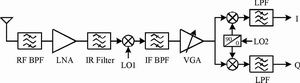
Figure 1 Block diagram of superheterodyne receiver
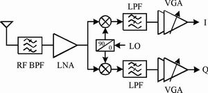
Figure 2 Block diagram of zero IF receiver
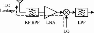
Figure 3 Schematic diagram of zero-IF local oscillator leakage
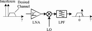
Figure 4 Interference of strong interference signals under even distortion
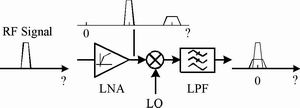
Figure 5 : Interference generated by RF signal with even distortion
Â
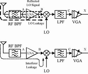
Figure 6 (a) Local oscillator leakage self-mixing (b) interference self-mixing
Â
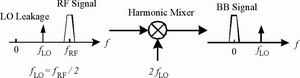
Figure 7 How the harmonic mixing circuit works