This article refers to the address: http://
1 power circuit works
TCL's IPL32C "two-in-one" power board power supply circuit, as shown in Figure 1. 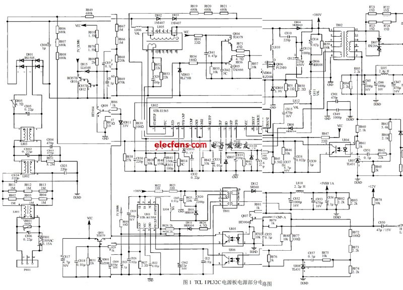
It consists of three parts: one is the PFC power factor correction circuit composed of 1/2 of the STR-E1565; the other is the +12V main power supply circuit composed of the other 1/2 of the STR-E1565, to the main board Provide +12V voltage; third is the +5VSB/1A auxiliary power supply with STR-A6159M as the core. After the power is turned on, the auxiliary power supply first works, providing +5V power supply to the main circuit board control system, and providing VCC working voltage for the STR-E1565, and the PFC power factor correction circuit and the +12V power supply are restarted.
1.1 +5V auxiliary power supply
In the IPL32C "two-in-one" power supply board, the sub-switching power supply circuit consists of: thick film circuit U801 (STR-A6159M), switching transformer T801, sampling error amplifier circuit U808 (TL431), optocoupler U806 and other components (see figure 1). The sub-switching power transformer T801 has two sets of voltage outputs at the "cold end" and "hot end": one is to output +5VSB/1A voltage on the cold ground, to supply power to the microprocessor control system on the main board; There is a set of voltage output at the end, which not only provides the working voltage for the secondary power supply U801 voltage regulator circuit, but also provides the VCC working voltage for the PFC correction circuit and the +12V main power drive control circuit.
   1.1.1 Starting the work process
AC220V mains via delay fuse F801 and C806, L801, C824, L802, C802, C803, C804, C805, L803, C805 constitute an AC anti-interference circuit, filter out high-frequency interference signals in the mains, sent to D801 The rectification and filtering circuit composed of C808 generates a pulsating DC voltage. Since the filter circuit capacitor C808 has a small capacity, the voltage load is about 300V when it is light, and about 230V when the load is heavy.
The pulsating voltage is charged by the PFC inductor L805 and the diode D804 to the filter capacitor C812, and generates a PFC-OUT DC voltage of about 300V. After the PFC circuit works, it rises to about 380V, and supplies power to the auxiliary power source and the main power source; R867, R866, R868 and R869 are divided, and the starting voltage is supplied to the 5th and 2nd pins of the auxiliary power supply U801 via D815 and R889. In addition, the 380V DC voltage is applied to the U801's 7, 8 through the primary 1~3 winding of the switching transformer T801. The pin supplies power to the D pole of the internal MOSFET switch. After the auxiliary power supply starts, an excitation pulse is generated to drive the internal MOSFET switch to operate in the switching state, and an induced voltage is generated in each winding of the T801.
After the sub-switching power supply starts working, the ripple voltage induced by the windings of the thermal grounding terminals 4 to 5 of the sub-switching transformer T801 is rectified by D811, filtered by C862, and sent to the 2nd pin of U801 via R888//R894 as the secondary power supply U801. The working power supply, U801 then enters the normal continuous operation; the other is sent to the c-pole of the standby control circuit V801, which is controlled by the standby control circuit to provide the VCC operating voltage for the PFC driving circuit and the main power driving circuit U802.
The induced voltage of the cold grounding secondary winding of T801 is rectified by D812. After filtering by C852, L818, C853 and C854, it generates +5VSB/1A voltage to supply power to the motherboard microprocessor control system.
1.1.2 Voltage Control Circuit
The voltage regulation control circuit is composed of an error amplifier U808, a photocoupler U806, and a 4-pin internal circuit of the thick film circuit U801.
When the voltage of +5VSB/1A of the sub-switching power supply is increased for some reason, the voltage is sampled by R872, R873 and R874, and the voltage of pin 1 of U808 is increased. After being amplified by U808, the voltage of the 3 terminal is lowered. The internal light-emitting diode of the optocoupler U806 is enhanced in illumination, and the internal resistance of the phototransistor is lowered. The voltage of the 4-pin of the U801 is pulled low. After the internal control of the 4-pin is stabilized, the excitation square wave of the U801 is narrowed, and the switch is turned on. When the time is shortened, the output voltage of the sub-switching power supply drops to the normal value; when the voltage of the +5VSB/1A output of the sub-switching power supply decreases, the above-mentioned circuit works in reverse, the conduction time of the switching tube is prolonged, and the output voltage of the sub-switching power supply rises to a normal value.
1.1.3 On/Off Control Circuit
The on/off control circuit is composed of a triode Q807, a photocoupler U805, and a VCC voltage control circuit Q801. The on/off (ON/OFF) control voltage of the main board control system is sent to the power board via the connector and applied to the b pole of Q807.
When the power is turned on, the main circuit board control system sends the ON/OFF voltage to the power board to a high level, Q807 is turned on, the "optocoupler" U805 internal light emitting diode emits light, and the "photocoupler" internal photodiode guide Pass, provide the forward bias voltage for the base of U801, Q801 is turned on, the VCC voltage provided by the sub-switching power supply is output through Q801, and sent to the PFC circuit and the roller of the +12V power supply driving circuit U802 to provide The operating voltage causes the main switching power supply to start working. The 12V working voltage is provided for the main circuit of the liquid crystal color TV, and the whole machine enters the boot viewing state.
When the remote control is turned off, the main circuit board control system sends the ON/OFF voltage of the power board to a low level, which turns off Q807, "optocoupler"
When U805 is cut off, the transistor Q801 is also cut off, and the working voltage of the PFC circuit and the main switching power supply U802 is cut off, so that the main switching power supply stops working and the whole machine enters the standby state.
1.1.4 Overvoltage protection circuit
The +5V sub-supply overvoltage protection circuit consists of 33V Zener diodes VD811, Q809, Q812, Q810, and controls the 2 pin and 5 pin supply voltages of the sub power supply integrated circuit U801. When the output voltage of the auxiliary power supply rises, the VCC voltage of the 4~5 windings of T801 will also rise. When the voltage rises to 33V, VD811 will be broken down, and Q809, Q812 and Q810 will be turned on one after another. Among them, the Q810 is turned on, and the power supply voltage of the 2nd and 5th pins of the sub-power supply U801 is pulled down by R889, the auxiliary power supply stops working, and no +5V voltage and VCC voltage output are output, so that the whole machine stops working.
1.2 PFC power factor correction circuit
The PFC power factor correction circuit is a new type of circuit inserted between the rectifier circuit and the filter circuit, and is actually an AC/DC converter.
It extracts the higher harmonic components of the rectified DC current and corrects it to a sine wave or a nearly sine wave. On the one hand, it suppresses the rectified higher harmonic components and reduces the interference of higher harmonics on the power supply; On the one hand, it makes full use of the grid power and provides the efficiency of the power supply.
The power factor correction circuit of the power supply is composed of a storage inductor L805, a drive circuit Q804, a Q805, a field effect MOSFET switch tube Q806, and a drive control circuit STR-E1565 of 3, 4, 5, 6, 7, 10, and a roll inside and outside. Circuit and other components.
5G Outdoor CPE (Customer Premises Equipment) refers to 5G user terminal equipment used in outdoor environments. It is a device that connects to a 5G network and provides wireless network connectivity, which can be used in various scenarios such as homes, businesses, and public places. The features and advantages of 5G Outdoor CPE are described in detail below.
First, features:
1. High-speed connection: 5G Outdoor CPE uses 5G technology, with higher transmission rates and lower latency. It can provide faster download and upload speeds than 4G networks, meeting users' needs for high-speed networks.
2. Large capacity: 5G Outdoor CPE supports more device connections, which can meet the needs of multiple users at the same time. It provides a higher network capacity and supports more terminal devices. It is suitable for scenarios where multiple devices need to be connected to a home or enterprise.
3. Wide coverage: 5G Outdoor CPE has wider coverage, which can provide better signal coverage and stability. It is suitable for outdoor environments and can provide better network connectivity in outdoor locations, whether in urban, rural or remote areas, with good signal coverage.
4. High reliability: 5G Outdoor CPE adopts a variety of technologies to improve network reliability, such as Multiple-Input Multiple-Output (MIMO) technology and Beamforming technology. It can provide a more stable and reliable network connection and reduce the risk of network outages and failures.
5. Flexible deployment: 5G Outdoor CPE can be flexibly deployed according to actual requirements. It can be installed on the exterior walls of buildings, roofs, telephone poles, etc., to maximize signal coverage. At the same time, 5G Outdoor CPE also supports a variety of installation methods, such as wall hanging, pole, etc., to adapt to different installation environments.
6. Simplified management: 5G Outdoor CPE supports remote management and monitoring, and can centrally manage devices through the cloud platform. Administrators can monitor device running status, troubleshoot and upgrade devices anytime and anywhere to improve management efficiency and O&M effect.
2. Advantages:
1. High-speed network experience: 5G Outdoor CPE can provide faster network speed and lower latency, and users can enjoy a smoother network experience. Whether watching HD videos, playing online games or downloading large files, you can get faster response times and higher transfer rates.
2. Multi-device connection: 5G Outdoor CPE supports more device connections, which can meet the needs of multiple devices in homes, enterprises and other places to access the Internet at the same time. Whether it is a smartphone, tablet, TV, camera or other smart device, it can be connected to the network through 5G Outdoor CPE to achieve connectivity.
3. Stable and reliable: 5G Outdoor CPE uses a variety of technologies to improve network stability and reliability. It can provide a more stable network connection by automatically selecting the best channel and automatically optimizing the signal. At the same time, 5G Outdoor CPE also supports backup and failover functions. When the primary device fails, it can be automatically switched to the standby device to ensure network continuity and stability.
4. Wide coverage capability: 5G Outdoor CPE has a wider coverage range, which can provide better signal coverage and expansion capability. It can cover a larger area and meet the network needs of different places. Whether in urban, rural or remote areas, you can get a stable Internet connection.
5. Flexible deployment and management: 5G Outdoor CPE can be flexibly deployed and managed according to actual requirements. It can be installed in different locations to maximize signal coverage. At the same time, 5G Outdoor CPE supports remote management and monitoring, and can centrally manage devices through the cloud platform, improving the management efficiency and operation and maintenance effect of devices.
In SUMMARY:
As a 5G user terminal device used in Outdoor environments, 5G Outdoor CPE has the features and advantages of high-speed connection, large capacity, wide coverage, high reliability, flexible deployment, and simplified management. It can provide faster network speed and lower latency to meet the needs of users for high-speed network; Support more device connections to meet the needs of multiple users at the same time; With wider coverage, providing better signal coverage and stability; Use a variety of technologies to improve network reliability and reduce the risk of network outages and failures; It can be flexibly deployed according to actual requirements to adapt to different installation environments. Supports remote management and monitoring, improving device management efficiency and O&M effect. The emergence of 5G Outdoor CPE will further promote the development of 5G networks and provide users with a better network experience.
5G Outdoor Cpe,Outdoor 5G Cpe,Router 5G Cpe,Wireless Ap Router 5G Cpe
Shenzhen MovingComm Technology Co., Ltd. , https://www.szmovingcomm.com